 English



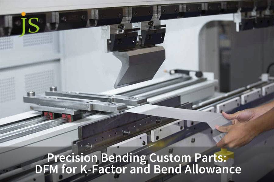

Precision bending custom parts is the fabrication of sheet metal where the neutral axis displacement ratio (K-Factor) and bend allowance (BA) are precisely controlled so that a manufacturing tolerance of ±0.1 mm flat pattern accuracy is achieved. Precision bending directly eliminates assembly interference and multiple trial die costs by compensating for the amount of material stretching in the plastic deformation zone in advance.
Precision Bending Custom Parts: Core DFM Parameter Matrix
|
Parameter |
Standard Range |
DFM Objective |
Impact on Accuracy |
|---|---|---|---|
|
K-Factor (K) |
0.30 – 0.50 (Air bending typical 0.44) |
Locate neutral axis plastic shift |
Determines flat pattern length, eliminates single-bend deviation |
|
Inside Radius to Thickness Ratio (R/t) |
≥ 1.0 (High-strength Al/SS ≥ 1.5) |
Eliminate inner crack and stabilize K value |
Prevents grain boundary tearing and micro-cracks |
|
Minimum Flange Height (Hmin) |
≥ 2t + R + 2 mm |
Ensure full contact on die shoulders |
Prevents slipping and flange dimension error |
|
Hole-to-Bend Safety Distance (Dmin) |
≥ 2.5t + R (Clinching features ≥ 3t + R) |
Isolate plastic deformation stretch zone |
Eliminates hole distortion and loose clinching |
Process conclusion:
The bending method of air bending means that the final formed inner radius mostly depends on the opening width of the lower die (R ≈ V/6). Using an identical inner radius across all parts will not only limit the frequency of die changes but also enable the production cost to decrease by over 20%.
How to Calculate Flat Patterns with K-Factor Sheet Metal?
K-Factor sheet metal is the ratio of the distance from the neutral axis to the inner surface divided by the total material thickness, which directly determines the flat pattern length. When the bend radius-to-thickness ratio (R/t) changes, the K value shifts nonlinearly between 0.30 and 0.50.
K-Factor Physical Definition and Neutral Layer Displacement Mechanism
The neutral layer is a thin surface in the curved section which is not under compression or tension. When R/t decreases the neutral layer moves closer to the inner surface and with that K value becomes less also.
- Air bending: the K value is generally 0.33–0.44, depending on the lower die opening and upper die cut depth.
- Bottoming: K value is around 0.50 overall material is pressed into a die with the help of pressure so that it is molded and the neutral layer is usually between two extreme faces.
Deviation between CAD expansion factor settings and actual workshop measurements
The default K value of 0.50 found in CAD software is actually rather inaccurate for the average working situation. Per the hands-on experience of JS Precision with precision sheet metal bending projects, when the default parameter is directly used, the error for a single bend can be 0.3–0.8 mm, the total error from multiple bends can easily be so large that parts will be practically useless.
ISO 2768-1:1989 sets the linear dimensional tolerance limits for medium grade (m grade) as ±0.30 mm with angular tolerance of ±0.5° at a size between 30–120 mm.
We adopt the K value that was measured instead of using the software default in the flat pattern. The single-fold deviation is controlled to be within ±0.05 mm to make sure that metal bending service delivery accuracy is ensured.
Neutral layer calculation formula and engineering application
A general method for determination of the neutral layer location is given as tn = K × t, where tn is the distance from the neutral layer to the inner surface while 't' is the sheet material thickness. Assuming that a bending operation takes place for a 90° bend, it would be necessary to calculate the flattened length L = A + B + BA, where BA = (π/180) × θ × (R + K × t).
Not sure about the measured K-Factor value of your material? Contact us for free trial bending and calibration services, and we will provide an exclusive expansion coefficient table based on your sheet and die opening.
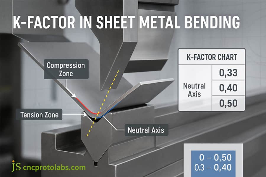
Figure 1: K-factor in sheet metal bending chart and zones.
What is the Difference in Sheet Metal Bend Allowance and Deduction?
Sheet metal bend allowance (BA) is the actual arc length of the neutral axis in the bend region, while the bend deduction (BD) is the difference between twice the outside setback and BA. Both calculate the same flat pattern dimension using different mathematical approaches.
Standard calculation formulas and parameter definitions
BA = (π / 180) × θ × (R + K × t)
BD = 2(R + t) × tan(θ / 2) - BA
Where θ is the bending angle (degrees), R is the inner fillet radius (mm), K is the K-Factor, and t is the plate thickness (mm).
Conversion logic between CAD and CNC control systems
Drafting programs, like SolidWorks, and other CAD software usually run on the BA algorithm, where press brake (CNC bending machine) control systems like Delem and AMADA normally take BD values. The incorrect switching of the two values causes the discrepancy in blanking sizes.
- 1.5 mm SPCC low carbon steel: 90° bend, R = 1.5 mm, K = 0.42, BA = 2.36 mm, BD = 3.64 mm.
- 2.0 mm 5052-H32 aluminum alloy: 90° bend, R = 2.0 mm, K = 0.43, BA = 3.14 mm, BD = 4.86 mm.
- 3.0 mm SUS304 stainless steel: 90° bend, R = 3.0 mm, K = 0.39, BA = 4.71 mm, BD = 7.29 mm.
JS Precision advises engineers to always indicate bending parameter references (BA or BD values) when drawing outputs, to prevent component interferences during fabrication and assembling, and above all, so that precision bending custom parts are produced as the first passes.
Do you want a bending deduction table that has been tested in the workshop? Submit your list of commonly used materials to us, and we will generate BA/BD comparison data that matches the actual equipment for you.
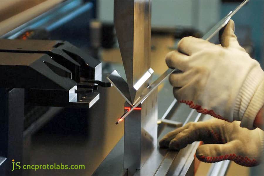
Figure 2: Worker measuring bent sheet metal part with tool.
How to Select Materials for Custom Metal Bending Service?
Bending cracks primarily occur when the bend line is parallel to the rolling grain direction, causing the tensile stress on the outer fiber to exceed the ultimate tensile strength. Using perpendicular grain direction reduces the minimum allowable bend radius by 30% to 50% for custom metal bending service .
Difference in forming limits between lateral and longitudinal bending
The minimum allowable R/t for 6061-T6 aluminum alloy is 3.0 when bending along the grain direction but can be reduced to 1.5 when bending against the grain. The difference is just about the same case of 304 stainless steel: a longitudinal bending R/t ≥ 2.0 and a transverse bending R/t ≥ 1.0.
The standard ASTM E290-22 mentions that in the ductility bending test, the critical value R/t for transverse bending is ≥ 1.0, whereas the critical R/t for longitudinal bending is ≥ 2.0.
JS Precision prefers to lay out horizontal bends when making material arrangements and marks grain directions of the sheets in drawings clearly so that mass production yield becomes much higher from 87% to over 97%.
Comparison table of minimum inner radius for longitudinal and transverse bending of common sheet metal materials
|
Material |
Longitudinal R/t |
Transverse R/t |
Crack Risk (Longitudinal) |
Crack Risk (Transverse) |
|---|---|---|---|---|
|
5052-H32 Aluminum |
2.0 |
1.0 |
Medium |
Low |
|
6061-T6 Aluminum |
3.0 |
1.5 |
High |
Medium |
|
SPCC Low-Carbon Steel |
1.0 |
0.5 |
Low |
Very Low |
|
SUS304 Stainless Steel |
2.0 |
1.0 |
Medium |
Low |
According to ASTM E290-22, the critical R/t for transverse bending is ≥ 1.0.
Local annealing and layout optimization of cold work hardening materials
In custom metal bending service, after being informed by customer requirements that we are dealing with very highly work-hardening (i.e. difficult to bend) materials like 304 stainless steel, local annealing is done pretreatment to lower the critical bending radius by about 20%. At the same time, via nesting optimization, the angle between the grain orientation and bending line is kept within 90° ± 15°.
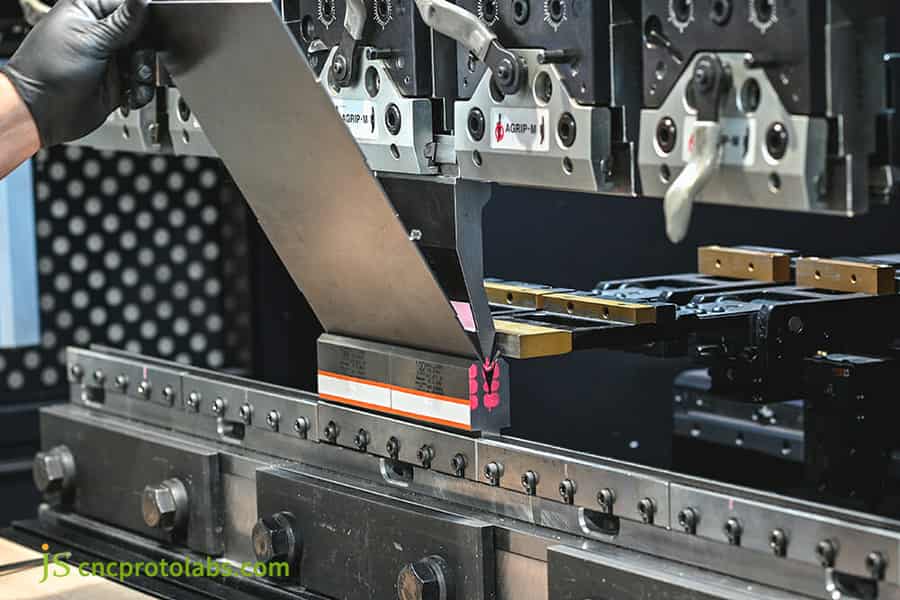
Figure 3: Worker feeding metal sheet into press brake machine.
How to Optimize Bend Radius Design and V-Die Selection?
In air bending, the actual inside radius is not determined solely by the punch tip but naturally forms at one-sixth of the die opening width (R ≈ V/6). Industry standards recommend a die opening V of 6 to 8 times the material thickness for optimal bend radius design .
Natural Rounded Corner Forming Rules and Design Misconceptions
Many engineers get mistaken thinking that the fillet radius of the upper die tip and the inner fillet radius of the workpiece are identical. Actually, in air bending, the inside fillet radius is the result of the opening V of the lower die: R ≈ V/6. When the sheet metal is in contact with the lower die (bottom bending) only then the inner fillet radius and that of the upper die are close enough.
DIN 6935 standards state that in case of cold formed flat steel products at rounded corners the thickness shall be about 20% less and that cross bending shall be preferred to longitudinal bending if possible. It is also mentioned that for thickness of S275JR steel plates of 6 mm, minimum permissible bending radius is 10 mm.
JS Precision has unified the rounded corners of all parts in bend radius design, reducing diechanges by over 60% and overall processing costs by 20%–25%.
The impact of die selection on surface quality and tonnage
- If the V value is too small (V < 5t), the deeper surface indentation will necessitate machine tool tonnage requirement increase by 30%–50%.
- If the V value is too large (V > 12t), the dimensional tolerances will be out of control and springback angle will become greater.
We strictly follow the principle of V = 6t–8t when it comes to sheet metal bending service. This method is implemented to keep consistency and high surface quality in batch production.
Have you finalized your bending die selection? Get free die matching assistance from us and we will suggest the most suitable combinations of V-opening and avoiding cavity, keeping your plate thickness and inner corner radius as references.
What are DFM Bending Guidelines for Hole Features?
The standard design rule to prevent feature deformation near bends is to maintain a hole edge distance of at least 2.5t + R from the bend tangent point. If space is limited, bend relief slots must be added at both ends of the bend line according to DFM bending guidelines .
Stress distribution in the plastic deformation zone
When metal sheet is bent, the transverse flow stress that is produced in the deformation area follows a non-linear trend. When the hole is located in the external tensile zone, stretching of the material pulls on the edge of that hole thereby enlarging it into an ellipse.
- Through holes and countersunk holes: Safety distance ≥ 2.5t + R.
- Long, narrow opening: Safety distance ≥ 3.0t + R.
- PEM press-fit nut bottom hole: Recommended ≥ 3t + R, to be able to prevent loosening after installation.
Tear-resistant groove size design specifications
JS Precision lists the recommended tear-resistant groove standards below in its DFM bending guidelines:
- Rectangular Relief: The groove depth equals or exceeds R + t, groove width is equal or larger than t or 1.5 mm, whichever is greater.
- Round Relief: Diameter ≥ 2t (t is a material thickness), center is placed on the extension line of the bend.
Planning the anti-tear structure during the design stage for precision metal instrument chassis will help to reduce more than 85% of the reworks during assembly and maintain a good thread fit between a precision bending custom parts and tool.
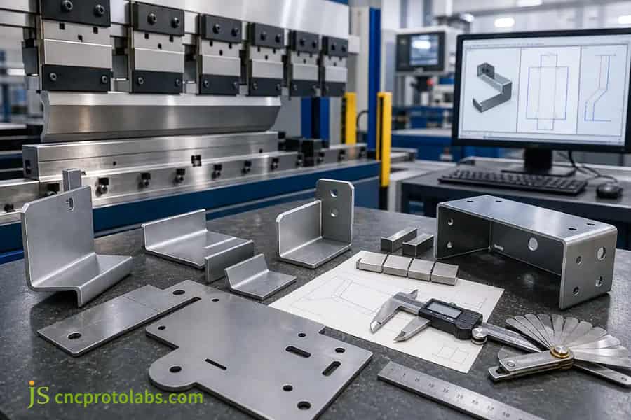
Figure 4: Bent metal parts with caliper and CAD design drawing.
How to Calibrate a Bend Deduction Chart for Metal Bending Service?
Calibrating sheet metal bending data requires performing physical test bends on standard coupons, measuring the flat pattern length, formed external dimensions, and springback angle to establish a bend allowance chart that matches the actual machine and tooling.
100 mm Standard Calibration Test Piece Prototype Process
- Cut 100 mm × 50 mm test pieces and measure the actual thickness t.
- Bend 90° on the selected V-mouth lower die and record the depth of the upper die pressing.
- Measure the external dimensions A and B after forming, and calculate the actual BA=A+B -100.
- Reverse calculate K=[BA × 180/(π× θ) − R]/t (where θ=90 °).
JS Precision Commonly Used Sheet Materials 90° Bend Deduction Chart and K-Factor Actual Measurement Comparison Table
|
Material |
Thickness (mm) |
V-Die (mm) |
Measured K |
BD (mm) |
|---|---|---|---|---|
|
SPCC |
1.0 |
8 |
0.445 |
1.72 |
|
SPCC |
2.0 |
14 |
0.438 |
3.46 |
|
SPCC |
3.0 |
20 |
0.431 |
5.31 |
|
5052-H32 |
1.5 |
10 |
0.452 |
2.54 |
|
5052-H32 |
2.0 |
14 |
0.446 |
3.59 |
|
6061-T6 |
2.0 |
14 |
0.421 |
3.82 |
|
6061-T6 |
3.0 |
20 |
0.415 |
5.74 |
|
SUS304 |
1.5 |
10 |
0.408 |
2.79 |
|
SUS304 |
2.0 |
14 |
0.396 |
4.17 |
|
SUS304 |
3.0 |
20 |
0.385 |
6.34 |
Sources: JS Precision 2025 shop floor calibration report (Test batch No. JS-TR-2025-SM08); International Organization for Standardization (ISO) — ISO 2768-1:1989, General Tolerances for Linear and Angular Dimensions.
Multi-fold cumulative tolerance and datum selection
JS Precision uses an innovative metal bending service strategy that reverses the back gauge reference from the blank edge to the inner bending edge. This technique is integrated with a laser online angle measurement system and dynamic hydraulic crowning, so angular deviation is removed at both ends of long parts as well as variations in yield strength across different batches of raw materials. The sheet metal bending service process has become part of our daily practices, enabling rapid tool changes and consistent deliveries across diverse order profiles.
Case Study: Medical Enclosure by Custom Metal Bending Service
Through correcting the neutral axis K-Factor and optimizing relief structures, JS Precision successfully reduced the cumulative tolerance of a multi-bend medical enclosure from ±0.6 mm to ±0.08 mm, achieving a first-assembly yield of 99.4% for custom metal bending service.
Difficulties encountered by customers
The design of a 2.0 mm 5052-H32 aluminum alloy multi-fold housing of a European medical equipment manufacturer was the starting point. The problem was the direct use of the default CAD coefficients and making 12 consecutive reverse folds. Due to this approach, the blanking sizes differed by 1.4 mm, the holes were strongly out of line, and tear marks showed up at the hinge.
JS Precision Solution
- K-Factor Correction: Recheck the tensile yield characteristics of the material and correct the theoretical K-Factor from 0.50 to the measured value of 0.428.
- Die adjustment: lower bend die is adjusted from V = 12 mm to V = 16 mm, preventing grain-boundary microcracking and maintaining a consistent inner radius of R = 2.5 mm.
- Tear-resistant structure: A rectangular processing tear groove of 2.0 mm in width and 3.5 mm in depth is placed at the edge of the interference hole. A step-by-step bending springback compensation is carried out using a CNC digital dial caliper electro-hydraulic synchronous machine tool.
Lessons learned from failure
The initial trial bending ignored the thickness tolerance fluctuation of ±0.08 mm between raw material batches, resulting in a 0.8° deviation in the batch bending angle. Subsequently, JS Precision developed operational standards for measuring thickness and grouping the incoming sheet metal, as well as adjusting the bending compensation values accordingly.
Final result
- Dimensional tolerance: The cumulative dimensional tolerance of the finished product remains stable within the range of ±0.08 mm.
- Assembly efficiency: Assembly time has decreased by 45%.
- Scrap rate: The comprehensive trial die scrap rate has been reduced to 0.6%.
Sources: Deutsches Institut für Normung (DIN) — DIN 6935:2011, Cold Bending of Flat Rolled Steel Products; JS Precision quality management system (Report No. JS-QA-2025-MED04).
Need to optimize your sheet metal bending tolerances or address cumulative deviations from multiple bends? Send your CAD model and engineering drawings to us now, and our engineering team will provide a DFM assessment and quote within 24 hours.
FAQs
Q1: What is the most common K-factor used for precision sheet metal bending?
For air bending where the inner radius is approximately equal to the plate thickness (R/t ≈ 1), the industry-standard K-factor for low-carbon steel and aluminum alloys is 0.44. For high-hardness stainless steels or soft copper the K value ranges from 0.38 to 0.48 and should be corrected by trial bending for the actual die opening.
Q2: How does material springback affect the final precision bend angle?
When the material is unloaded from the bent shape, elastic strain recovery causes the angle to increase. The springback angle of 304 stainless steel can reach 2° to 5°, that of low carbon steel is up to 0.5° to 1°. The overbending compensation should be set on the CNC press brake before processing workpieces to lock the final angle tolerance.
Q3: Why do holes positioned too close to the bend line become distorted?
If the opening belongs to the plastic tensile deformation region on the outer sides of bend, the elongation of the material will draw the edge of the opening into an elliptical shape. The edge of opening to the bending tangent point distance should be 2.5t + R, or in design a tear-resistant groove should be in front of bend.
Q4: What is the difference between air bending and bottom bending in practice?
Air bending means resting on only 3 points: the tip of the upper die and the two shoulders of the lower die. The angle is controlled by the downward stroke and the inner radius R is controlled by the width of die opening (R: V/6). Bottoming (press-down bending) is a process of forcing the sheet metal completely into the die. Has high accuracy but 3 to 5 times of tonnage as air bending.
Q5: How does JS Precision guarantee tight bending tolerances on custom orders?
JS Precision achieves this using multi-axis linear encoders, electro-hydraulic servo CNC press brakes, and a laser-based online angle compensating system. These together will result in very tight linear dimensional tolerances which remain at ±0.1 mm and angular tolerances at ±0.5°. This is achieved by feed thickness sorting and test piece measurement compensation tables.
Q6: What engineering file formats are required for an accurate DFM and bending quote?
Provide STEP/IGES files containing 3D geometric entities, as well as 1:1 scale 2D DXF/DWG engineering drawings annotated with bending lines, material grades, plate thickness tolerances, grain direction requirements, and key assembly dimensions to obtain a quotation.
Q7: What factors determine the pricing of custom metal bending services?
The base price is calculated taking into consideration of material grade thickness laser cutting time, quantity of bending operations, costs of special forming dies to be amortized, and production lot. If the inner radius of a part is standardized, it will help avoid a lot of time wasted on switching dies and adjusting machines, and will bring the cost down by as much as 25% per unit.
Q8: Can very sharp inside bend radii (R < 0.5t) be manufactured reliably?
Extremely small inner radius (R < 0.5t) generates extremely high concentrated tensile stress on the outer side of the bend, which can easily induce grain boundary cracking and cause severe shift of the neutral layer. Except for specific structures and those that have undergone local annealing, engineering designs should maintain R ≥ t as much as possible.
Summary
The main factor for high quality in precision sheet metal bending is that accurate determination of the right material K-factor, bending deduction value and lower die opening must be made at the early phases. Avoiding parallel grain bending, and rational planning of safety distance of hole edges and process tear groove should be considered for eliminating more than 90% of trial die rework and assembly problem, and final part dimensions remain stable within tolerance.
To develop a new series of high-precision sheet metal structural components, upload your CAD models and production drawings (e.g.STEP or.DXF) to JS Precision. Through the efforts of our sheet metal producing specialist team, you will obtain a total DFM report and a quotation for mass production all within a period of 24 hours including unfolding verification, die selection, and cost optimization services to accelerate your time to market.

Disclaimer
The contents of this page are for informational purposes only. For JS Precision Services, there are no representations or warranties, express or implied, as to the accuracy, completeness, or validity of the information. It is the buyer's responsibility to identify specific technical requirements and request a formal parts quotation. Please contact us for more information.
Resource

