 English





Custom sheet metal fabrication assemblies fail for six recurring reasons: hole deformation near bends, tolerance stack-up, PEM fastener spin-out, welding distortion, coating seizure, and inverted assembly. Each one is a design-stage problem, not a shop-floor problem — which means each one is preventable before a single part is cut. Standard DFM(Design for Manufacturing) rules remove the bottleneck: keep holes ≥ 2T + R from bend lines, locate with a single datum pin plus a ±0.8 mm floating slot, add +75 μm to +125 μm unilateral clearance for coating, and use tab-and-slot geometry for self-location.
5 Common Assembly Failures and Correction Parameters
|
Assembly Failure Type |
Root Cause |
DFM Correction Standard Parameter |
Assembly Yield Improvement |
|---|---|---|---|
|
Hole Deformation |
Hole edge falls into tensile strain zone |
Hole edge distance ≥ 2T + R; add relief slot ≥ 1.5T |
Roundness qualification rate ≥ 99% |
|
Tolerance Stack-up |
Linear tolerance accumulation across bends |
Single datum pin + floating slot ±0.8 mm |
Misalignment rework ≤ 1% |
|
PEM Fastener Spin-out |
Oversized pilot hole or hard base material |
Pilot hole tolerance +0.05 / -0.00 mm; hardness diff. ≥ 15 HRB |
100% pass at specified proof torque |
|
Welding Distortion |
Continuous weld heat input releases stress |
Tab-and-slot self-locating + intermittent weld |
Flatness deviation ≤ 0.4 mm (from 2.5 mm) |
|
Coating Seizure |
CAD nominal size ignores coating thickness |
Unilateral clearance +75 μm to +125 μm |
Onsite reaming eliminated |
|
Inverted assembly |
Symmetrical flat pattern fits two ways |
Offset hole group 3–5 mm / keyed notch / engraved direction arrow |
Reverse-install rework eliminated |
ASTM E290-22 defines the guided bend test used to determine how far a given alloy and temper can be formed before it cracks — the test that establishes the minimum inside bend radius (R) for each material. That R is the direct input to the hole edge distance ≥ 2T + R rule: once the bend test fixes R, the safe distance from the bend tangent to the hole edge follows from it.
Design-stage 3D modelling is the highest-leverage fix. When the CAD model accounts for bend-deformation mechanics, fastener pilot-hole accuracy and coating thickness at the same time, secondary rework and trial-assembly losses can be reduced to near zero — and in most cases removed entirely — before the assembly stage ever begins.
Why Do Flange Holes Distort in Custom Sheet Metal Fabrication?
In custom sheet metal fabrication, placing fastener holes too close to bend tangent lines exposes the metal around the hole to severe tensile stress during press-brake forming, stretching circular holes into ovals and pushing mounting points out of position. The distortion happens inside the plastic deformation zone, where the outer fibres of the sheet stretch past their elastic limit and the hole is dragged along with them. To guarantee fastener alignment in any precision workflow, the distance from the hole edge to the bend tangent must be at least two times the sheet thickness plus the inside bend radius (≥ 2T + R).
Common Plate Hole Edge Distance and Relief Slot Parameter Table
|
Thickness (mm) |
Material |
Inside bend radius R (mm) |
Calculated minimum L = 2T + R (mm) |
Recommended design value (mm) |
Relief Slot Width (≥1.5T) (mm) |
Relief Slot Depth (mm) |
|---|---|---|---|---|---|---|
|
1.5 |
5052-H32 |
0.80 |
3.80 |
4.30 |
2.25 |
0.75T |
|
2.0 |
SPCC |
0.80 | 4.80 | 5.30 |
3.00 |
0.75T |
|
3.0 |
5052-H32 |
1.05 | 7.05 | 7.55 |
4.50 |
0.75T |
ASTM B209/B209M-21a specifies the alloys, tempers, and cold-bend capability of aluminum and aluminum-alloy sheet and plate, validating the 5052-H32 material parameters and their minimum bend radii for hole-to-bend distance calculations.
The recommended design value adds a 0.5 mm margin to the calculated minimum to cover material-thickness variation and bend-radius drift across a production run. If your layout cannot meet the recommended value, treat the calculated minimum L = 2T + R as the hard floor and add a relief slot.
How tension on the outer fibre pulls holes out of round
5052-H32 aluminum and SPCC cold-rolled steel in the 1.5 mm to 3.0 mm thickness range are the most likely to show out-of-round holes after bending. During forming, the outer fibres of the bend are pulled into tension while the inner fibres are pushed into compression, and any hole sitting inside that tension band is stretched along the bend axis — it comes off the brake oval instead of round.
When a compact layout makes the minimum clearance impossible, add one more feature rather than accepting the risk: cut a relief slot into the flat pattern, inboard of the bend line and aligned with the bend tangent, sized to the rule below.
L ≥ 2T + R, W ≥ 1.5T
Where L is the safety distance from the hole edge to the bend tangent line, T is the sheet thickness, R is the inside bend radius, and W is the relief slot width.Holding L at or above this limit stops plastic flow from dragging the hole out of round during forming, so bolts and pins seat without being forced.
Relief slot design specifications and subsequent hole enlargement
- If a relief slot cannot be added to the flat pattern, machine the hole after bending. Open it to a size that gives the bolt or pin free passage, and call the post-bend operation out on the drawing so the shop does not have to guess.
- Laser cutting reproduces the relief-notch profile accurately and repeatably, so the slot itself introduces no additional deformation.
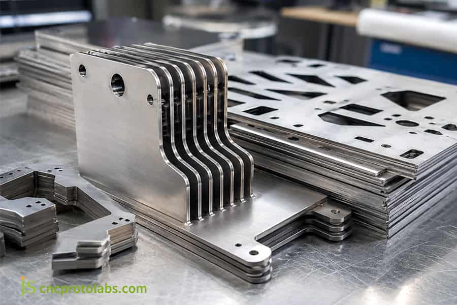
Figure 1: Press-brake-formed custom sheet metal brackets, showing the laser-cut relief slot at each bend line.
How Does Cumulative Tolerance Stack Ruin Sheet Metal Assembly Design?
Tolerance stack-up compromises sheet metal assembly design when the individual variances from shearing, laser cutting and successive CNC press-brake operations accumulate across consecutive flanges. Sheet metal forming carries natural material variation — grain orientation and elastic springback above all — producing linear variances of about ±0.2 mm and angular variances of about ±0.5° per bend.Without datum-driven dimensioning, five sequential bends accumulate more than ±1.0 mm of positional shift from linear error alone, and past 1.5 mm once the angular error is included. At that point the mounting holes simply stop lining up.
How tolerance accumulates in a multi-bend box
- Tolerances stack in more than one axis. Linear and angular deviations compound across a chain of flanges. Under a worst-case stack, the cumulative offset of a five-bend box exceeds 1.5 mm, and mass-production pass rates fall with it.
- RSS narrows the number; it does not fix the problem. A root-sum-square calculation predicts a smaller, statistically likely spread — but the underlying variation is still there. The durable fix is to re-establish the assembly positioning datum.
- Consolidate every locating surface into one datum. Replace multi-edge alignment with a single main datum pin hole, and cut a mating ±0.8 mm oblong slot in the second panel to absorb the remaining error band.
Floating-datum DFM strategy and machine-side compensation
Our press brakes use real-time laser angle compensation, holding bend angles across multi-bend parts to within±0.2° and pushing first-time fit rates above 99%. The mating oblong slot then provides ±0.8 mm of float, which absorbs the residual stack-up instead of fighting it.
Across more than 1,200 European projects in JS Precision's internal quality database, this datum-reconstruction method raised first-pass assembly yield from 82% to 99.1%. The lesson is a costing one: datum design, not tighter part tolerances, is the most cost-effective lever in sheet metal assembly design.
Comparison Table of Traditional Assembly Design for Sheet Metal Enclosures vs. Floating Baseline DFM Design
|
Comparison Dimension |
Traditional Assembly Design |
Floating Datum DFM Design |
|---|---|---|
|
Positioning Method |
Multiple surface alignment |
Single datum pin + oblong slot |
|
Tolerance Absorption |
None — error accumulates along the chain |
±0.8 mm slot absorbs stack-up |
|
Single Part Cost |
Lower to cut, higher to assemble |
Slightly higher to cut (one extra slot feature) |
|
Assembly Time |
Longer; fitting and rework on the line |
Shorter; panels drop straight into place |
|
Dedicated fixture needed |
Yes |
No — the geometry self-locates |
|
Rework Rate |
8–18% on five-bend enclosures |
≤ 1% |
Datum-pin positioning and the ±0.8 mm floating slot are applied using ASME Y14.5 datum-reference-frame principles; general linear and angular tolerances on the cut blank follow ISO 2768-1. The ±0.8 mm float value itself is not a standard-mandated number — it is a JS Precision DFM default derived from the measured stack-up of a five-bend enclosure, sized to cover the worst-case band calculated above with margin to spare.
Next step: upload your STEP or IGES file and JS Precision will return a DFM review plus a laser-cutting quotation within 24 hours — including a side-by-side comparison against mechanical drilling where hole quality or hole position is critical.
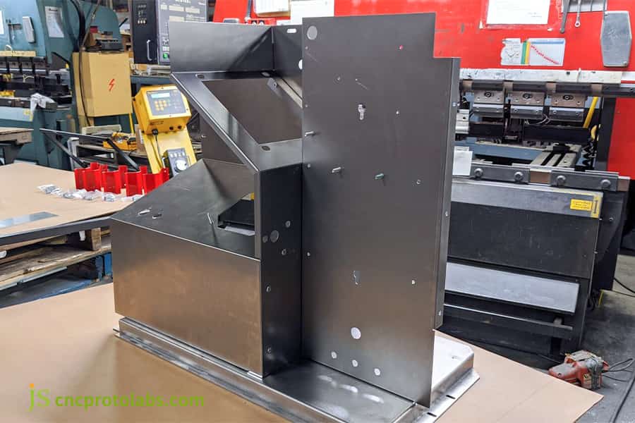
Figure 2: Sheet metal enclosure prototype built with a single datum pin and ±0.8 mm oblong slots on the base flange.
What Mechanical Flaws Cause Clinch Fasteners to Spin Out?
Clinch fastener blowouts, rotation and pull-out failures happen for three main reasons: the pilot hole is laser-cut oversized, the sheet is too thin, or the base material is too hard to cold-flow into the fastener knurl. Self-clinching fasteners such as PEM nuts work by displacing sheet metal into an annular undercut, so the pilot hole diameter has to be held to +0.05 / −0.00 mm. Open the hole beyond that band — or install with the wrong tonnage — and push-out resistance drops by more than 60%, which is why fasteners spin or pop out under working torque.
Installation parameter specification table for press-fit fasteners
|
Base material |
Fastener |
Pilot hole ⌀ (mm) |
Pilot Hole Tolerance (mm) |
Hardness differential (HRB points) |
Edge Distance (≥1.5D) |
Installation Force (kN) |
|---|---|---|---|---|---|---|
|
SUS304 |
M4 self-clinching nut |
5.40 |
+0.05 / -0.00 |
≥15 |
1.5D |
22 |
|
SPCC |
M4 self-clinching nut |
5.40 |
+0.05 / -0.00 |
≥15 |
1.5D |
22 |
|
AL6061-T6 |
M4 self-clinching nut |
5.40 |
+0.05 / -0.00 |
≥15 |
1.5D |
22 |
|
AL5052-H32 |
M4 self-clinching nut |
5.40 |
+0.05 / -0.00 |
≥15 |
1.5D |
22 |
ASTM E8/E8M-22 defines tensile testing for yield strength and elongation — the properties that decide whether a base material can cold-flow into a fastener knurl without cracking. The ≥ 15 HRB hardness differential is measured separately by Rockwell hardness testing to ASTM E18, and the 22 kN installation force is the published value for M4 carbon-steel self-clinching nuts. Always confirm against the fastener manufacturer's current datasheet for other sizes and materials.
Values apply to M4 carbon-steel self-clinching nuts (e.g. PEM S/CLS series). D = across-flats diameter of the fastener hex. Installation force must be re-derived from the fastener manufacturer's current datasheet for any other thread size, fastener material or sheet thickness — do not carry 22 kN across by default.
Failure threshold and material matching of press-fit nut column
- Match hardness, or the fastener will not bite. For every base material we run in production — SUS304, SPCC, AL6061-T6 and AL5052-H32 — the mounting surface must be at least 15 HRB softer than the fastener itself.
- Never chamfer the pilot hole. A chamfer removes sheet thickness at exactly the point where metal has to flow into the undercut, and the joint loses its grip.
- Keep the hole centre at least 1.5 D from the sheet edge, where D is the across-flats diameter of the hex. Any closer and the displaced metal bulges and cracks the edge — one of the most expensive sheet metal assembly failures to discover at final assembly.
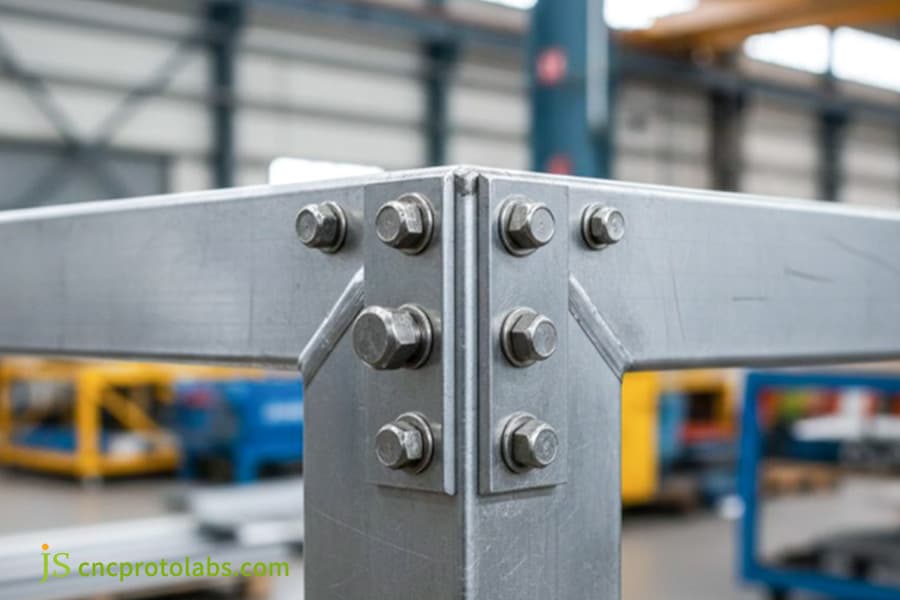
Figure 3: M4 self-clinching nut pressed into 2.0 mm 5052-H32 sheet, with the mating bolt fitted.
Can Tab-and-Slot Joints Prevent Distortion in Sheet Metal DFM?
Thermal distortion and joint misalignment appear when the concentrated, uneven heat of TIG or MIG welding releases residual stress in thin-gauge panels. A continuous seam along a long, thin panel creates a thermal gradient that bows the assembly outward — we measure flatness deviation of up to 2.5 mm on un-fixtured panels. Building self-locating tab-and-slot features into the flat laser-cut pattern removes the need for external jigs: the panels lock into alignment mechanically, and the weld length needed to hold the joint drops by about 50%.
Mortise and tenon jointing process and deformation differences
- Conventional welded assembly of thin panels (1.0 mm to 2.5 mm) is highly prone to heat distortion. A laser-cut, self-locating tab-and-slot joint holds the same panels to a flatness deviation of ≤ 0.4 mm.
- Size the joint to the sheet. Tab height equals material thickness T. Laser-cut the slot with +0.10 mm to +0.15 mm clearance, and add a 0.5 mm chamfer at each end so the tab enters quickly on the line.
- Weld less, and weld intermittently. Moving from a full-length seam to staggered intermittent welds at the load paths cuts total heat input by more than half.
The self-positioning structure saves on fixture costs.
Self-location pays twice: it removes the fixture and it removes the fitting time. Because the panels hold themselves in position during assembly, you avoid both the cost of building a dedicated alignment fixture and the lead time to design and prove it.The result is a frame that comes off the welder dimensionally accurate and consistent enough to meet IP55 sealing requirements.
Want to see how this works on real parts? Read JS Precision's process review on preventing aluminum sheet warping, or send us your flat pattern for a tab-and-slot review before you commit to tooling.
How Does Powder Coating Build-up Impact a Sheet Metal Fabrication Service?
Overlooking finishing thickness in the CAD model causes tight-tolerance holes to shrink, hinge joints to seize, and threaded fasteners to cross-thread at final assembly. Industrial powder coating deposits 60 μm to 120 μm per side; liquid spray adds 25 μm to 40 μm. Model slip-fit pins, slide rails and bearing holes at nominal size without allowing for that build-up, and the parts bind on the line — which then costs you onsite grinding, chemical stripping, and a sheet metal fabrication service call-out to sort it out.
The actual effect of coating thickness on assembly hole size
- Powder coating is the worst case. Electrostatic powder builds 60–120 μm per side, so an uncompensated hole loses up to 0.24 mm of diameter — more than enough to jam a slip-fit pin. Liquid spray is gentler at 25–40 μm per side.
- Compensate in the CAD model, not on the line. Anodizing, e-coating and plating all change the size of critical holes. As a working rule for additive finishes, allow 1.5× the specified single-side thickness in the model and state the requirement on the drawing. Anodizing behaves differently — it is a conversion coating that grows roughly half in and half out — so confirm the allowance with your finisher rather than applying the 1.5× rule to it.
- Worked example: a ⌀6.00 mm pin hole is pre-cut to ⌀6.25 mm. The pin still fits after coating, and nobody has to scrape paint off on site — which would break the coating and the corrosion guarantee along with it.
Engineering compensation process and shielding protection specifications
Masking is a drawing requirement, not a shop-floor decision. Wherever a threaded hole must stay to size, or a grounding point needs bare, conductive metal, the drawing has to call out high-temperature silicone plugs and polyimide tape explicitly. Specified at that stage, masking costs nothing. Skipped, it produces seized assemblies and hours of on-site hole and paint rework.
Worried about broken taps or stripped threads? Ask JS Precision for a threading review — in many enclosures, self-clinching nuts replace tapped holes outright and take the scrap risk out of the process.
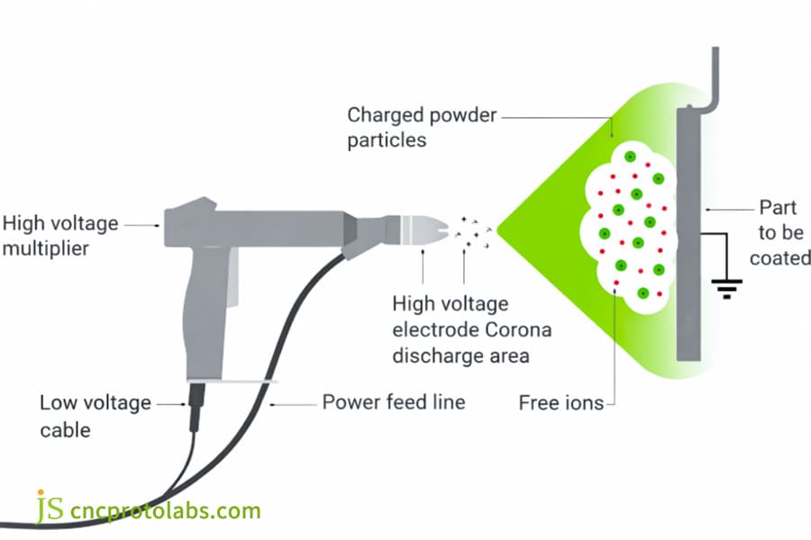
Figure 4: Powder coating build-up on a sheet metal assembly.
How Do Asymmetric Features Prevent Inverted Assembly on the Line?
Poka-yoke (error-proofing) features physically prevent an operator from mounting a part backwards or upside down on a high-speed line. Symmetrical or near-symmetrical sheet metal brackets look identical from both sides, which is exactly why they get installed reversed — misaligning internal components or pinching a wiring harness. Build deliberate asymmetry into the flat pattern, such as offsetting one set of mounting holes, adding a keyed notch, or staggering the tab spacing, and the parts can only ever go together one way.
Asymmetrical openings and foolproof chamfer design
- Offset a bolt hole group by 3 mm to 5 mm. Shifting the diagonal holes on one side produces an asymmetric pattern that cannot be rotated into the wrong position.
- Add a keyed notch at the plate edge. The notch mates with a matching stop on the base, so the panel physically seats in only one orientation.
- Mark the direction permanently. Laser-engrave a mounting-direction arrow and the part identification code into the surface during the same cutting pass — the marking adds no cost and survives painting.
- Use unidirectional hardware where you can. Orientation-specific press-fit nuts add a second, independent layer of mistake-proofing.
Eliminating human error at zero additional cost
All of this costs nothing at the part level.Because the asymmetry is designed into the 3D model and cut in the same laser pass, there is no added tooling, no extra operation and no added unit cost — yet reverse assembly, and the rework that follows it, disappears from the line.
How JS Precision Solved Fit-up Errors in Custom Sheet Metal Fabrication Service?
JS Precision delivered a zero-fit-up-error solution for a 5052 aluminum chassis — not by tightening part tolerances, but by re-engineering the DFM and assembly parameters.
Difficulties encountered by customers
- The brief. A European medical equipment manufacturer was pilot-building centrifuge analyzer housings. The first 50 sets of the 2.0 mm 5052-H32 aluminum chassis, produced by the previous supplier, could not be assembled.
- Holes missed by 1.8 mm. The screw holes in the four-sided bent top cover were out of position by up to 1.8 mm against the base, and the resulting uneven compression of the sealing strip failed the IP54 leak test.
- One fastener in four failed. The M4 clinch nuts inside the chassis spun out on 25% of units during torque assembly, stopping the line.
JS Precision Solution
- Datum reconstruction and tolerance decoupling. The four scattered bending datums in the original design were consolidated into a single locating pin surface, and every screw hole in the base plate was converted to a unidirectional oblong slot giving ±0.8 mm of compensation along its long axis.
- Bend-zone stress relief and tighter angle control. We recalculated the K-factor for this specific aluminum coil rather than using a generic value, so that flat-pattern development matched the real bend allowance. We also opened a 3.0 mm (1.5 T) relief cut at every bend and formed the parts on a CNC press brake with dynamic angle compensation holding deviation to ±0.15°.
- Fastener and coating correction. The clinch nut pilot hole was set to ⌀5.40 mm (+0.05 / −0.00 mm) and installed on a closed-loop press at a constant 22 kN. Separately, the powder coating thickness was fixed at 80 μm in the 3D model, and the grounding holes were plugged and masked before coating.
Lesson learned: grain direction only showed up at prototype stage
The original design ignored the effect of rolling direction on springback. We measured 1.2° more springback when the bend line ran parallel to the rolling direction than when it ran perpendicular to it. The rule we now apply at flat-pattern layout: never run a bend line parallel to the rolling direction — lay it out at 45° or 90° to the grain.
Final result
- 200 housings, 100% first-time fit. Assembly efficiency improved by 45%, and every unit passed the sealing test to IP55 — up from a failed IP54.
- Fastener torque reached 6.8 N·m, roughly 40% above the design requirement, which let the customer complete EC medical certification and start mass production on schedule.
This result matches the wider trend in our 2025 quality data: across similar multi-bend medical housings, first-pass yield rose from 82% to 99.1% once the datum scheme was rebuilt.
Want the same result on your chassis? Send JS Precision your 3D model and drawing, and our engineers will return the datum scheme, relief-slot layout and coating compensation you need for a first-time fit.
FAQs
Q1: What is the minimum recommended hole-to-bend distance in custom sheet metal fabrication?
Keep the hole edge at least 2T + R from the bend tangent line, where T is sheet thickness and R is the inside bend radius. If the layout cannot give you that distance, add a relief slot at least 1.5 T wide along the bend line. Held to this rule, fastener hole roundness stays within ±0.05 mm after forming.
Q2: How does powder coating thickness affect sheet metal fabrication service assembly fits?
Powder coating adds 60–120 μm per side, so an uncompensated hole loses up to 0.24 mm of diameter. Either pre-enlarge the hole in the design — we recommend +75 μm to +125 μm unilateral clearance — or mark the hole on the drawing for masking with high-temperature silicone plugs or polyimide tape so paint cannot enter it.
Q3: Why are my PEM fasteners spinning or popping out during final enclosure assembly?
Spinning is caused by an out-of-tolerance pilot hole, a base material too hard to cold-flow, or incorrect installation force. Hold the pilot hole to +0.05 / −0.00 mm, keep the base material at least 15 HRB softer than the fastener, and never chamfer the hole — a chamfer removes the metal that has to flow into the undercut.
Q4: How can I receive a fast and accurate custom sheet metal fabrication quotation from JS Precision?
Submit your STEP/IGES 3D model together with the 2D drawing. JS Precision returns a DFM evaluation within 24 hours and a transparent, tiered quotation covering both prototyping and production volumes.
Q5: What is the typical tolerance achieved by precision sheet metal fabrication service providers?
Standard laser cutting holds ±0.1 mm on the cut profile, and a press brake without compensation holds ±0.5° on bend angle. Two things tighten the formed result: real-time laser angle compensation brings the angle to ±0.2°, and verifying the K-factor for the actual material coil brings formed linear dimensions to ±0.2 mm. Those are the values assumed in the stack-up calculations in this article.
Q6: What is the tab-and-slot design method, and how does it lower manufacturing costs?
Tab-and-slot (also called mortise-and-tenon) design cuts a tab on one panel and a matching slot on the other, both in the same laser pass. The panels snap together before welding and hold themselves in position without a dedicated fixture. Flatness stays within ≤0.4 mm, and because welds become short and intermittent, total heat input falls by more than half — typically cutting assembly time by around 30%.
Q7: How do engineers calculate cumulative tolerance stack-up for multi-bend chassis?
Engineers use either the worst-case method or the root-sum-square (RSS) method. Worst case simply adds the individual tolerances: at ±0.2 mm of linear error per bend, five bends give ±1.0 mm of linear stack, and more than 1.5 mm once the ±0.5° angular error per bend is included. RSS returns a statistically smaller figure, but neither method removes the error — which is why the main locating hole is decoupled from the chain with a ±0.8 mm oblong slot that absorbs the residual stack-up.
Q8: Can aluminum sheet metal match the assembly rigidity of cold-rolled steel?
Aluminum's elastic modulus is about one third that of steel (≈69 GPa against ≈200 GPa), so an identical geometry is roughly three times more flexible.Because bending stiffness scales with the cube of thickness, increasing sheet thickness by 40–50% restores steel-equivalent stiffness while still cutting weight by about 40% (aluminum density ≈2.7 g/cm³ against steel's ≈7.85). Stamped ribs and return flanges recover the remaining stiffness without adding mass.
Summary
Misaligned holes and tolerance interference in custom sheet metal assembly almost always trace back to one thing: the drawing was produced without accounting for how the material actually behaves. The fix belongs at the drawing stage, and it is specific — keep hole edges ≥ 2T + R from bend lines, locate with a single datum pin plus an elongated ±0.8 mm slot to absorb accumulated tolerance, compensate 60–120 μm of coating per side in the 3D model, and use tab-and-slot joints to suppress welding distortion. Remove the geometric interference before the first part is cut, and you remove the line stops, the fixture rework and the on-site grinding along with it.
Don't let tolerance buildup delay mass production. Send your CAD drawings to the JS Precision engineering team and you will receive an in-depth DFM report and a transparent quotation within 24 hours — so your chassis fits the first time, straight out of the box.

Disclaimer
The contents of this page are for informational purposes only. For JS Precision Services, there are no representations or warranties, express or implied, as to the accuracy, completeness, or validity of the information. It is the buyer's responsibility to identify specific technical requirements and request a formal parts quotation. Please contact us for more information.
Resource

