 English



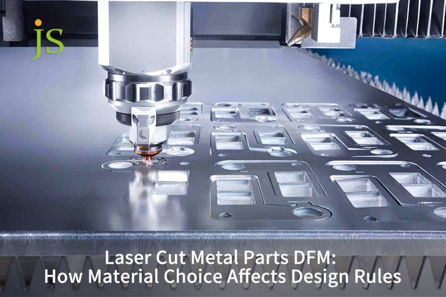

Laser cut metal parts DFM is the practical engineering method of tailoring CAD sheet-metal features — minimum hole diameter, web spacing and cut tolerance — to the actual cutting behaviour of each metal, so that parts are not scrapped or reworked. Stainless steel needs ≥ 1.5T web spacing to avoid warpage. Aluminum and copper need modified piercing parameters and nitrogen assist gas. Carbon steel leaves an oxide scale that must be ground off before coating.
Quick Reference: Laser Cutting DFM Rules by Material Category
|
Material Category |
Min Hole Diameter (Experience) |
Min Wall/Slot Spacing |
Assist Gas & Edge State |
Core DFM Challenge & Countermeasure |
|---|---|---|---|---|
|
Mild Steel / SPCC |
Thin sheet ≥ 0.8T; Medium ≥ 1.0T |
≥ 1.0T (and ≥ 1.5 mm) |
Oxygen (fast / black oxide) or high‑pressure N2 (bright) |
Corner burn‑through. Change sharp corner to R 0.5T or use loop path. |
|
Stainless Steel (SUS304/316) |
≥ 1.0T to 1.2T |
≥ 1.5T to 2.0T |
High‑pressure N2 (bright, slag‑free, weldable) |
Slow heat dissipation causes warpage. Increase hole distance and leapfrog cutting. |
|
Aluminum (Al 5052/6061) |
≥ 1.2T to 1.5T |
≥ 1.5T to 2.0T |
High‑pressure N2 or air (hard dross at bottom) |
Piercing explosion, reflection. Mark center for mechanical drilling. |
|
Brass / Copper |
≥ 1.5T to 2.0T |
≥ 2.0T to 2.5T |
High‑pressure N2 (18–25 bar) |
Extreme reflection & heat conductivity. Avoid dense holes, spacing ≥ 2.5T. |
ISO 9013:2017 (Thermal cutting — Classification of thermal cuts — Geometrical product specification and quality tolerances) grades laser-cut edges by quality range, using the mean profile height Rz5 rather than Ra.
Blueprints for such work can't rely on a one-size-fits-all approach. Decisions such as hole diameter and hole-to-edge distance depend partly on how much heat the material absorbs, together with its reflectivity and slag adhesion. These rules let the shop cut the part right the first time, with no rework.
Why Do Different Metals Require Unique Cutting Rules?
Laser cut metal parts DFM requires distinct cutting rules for each metal because thermal conductivity, optical reflectivity, and slag viscosity vary drastically across materials. Carbon steel cuts fast with oxygen but risks local overheating; stainless steel accumulates heat causing warpage; at the 1 µm fibre-laser wavelength and room temperature, copper absorbs only about 5% and aluminum about 10% of the incident beam, and both form hard, high-viscosity dross. Tailoring CAD spacing to these properties is the foundation of avoiding prototype scrap.
Difference between oxygen and nitrogen cutting processes
- In carbon steel, the iron–oxygen exothermic reaction supplies additional cutting energy, but it also leaves a 10–30 μm oxide layer on the cut surface that must be ground off before coating or welding.
- Stainless steel and aluminum alloys are cut by melting alone — no exothermic reaction — with slag flushed out by 14–20 bar of high-pressure nitrogen. The result is a bright, oxide-free edge that can go straight to welding.
- Adjusting CAD spacing to each material's characteristics is one of the most effective steps for preventing prototype scrap. A laser cutting design rule that does not state which material and thickness it applies to is not a rule — it is a guess.
Typical cases of unclassified materials being scrapped
- Carbon steel acute angle melting: oxygen-assisted combustion leading to a local thermal overload melts and even evaporates sharp corners causing dimensional changes or even structural failures.
- Stainless steel thin-strip bowing: stainless sheds heat slowly, so the whole sheet warps into a bow. Over a 1 m length, deflection commonly reaches 3–8 mm.
- Aluminum dross adhesion: deburring aluminum sheet is difficult because the molten metal re-solidifies on the underside as hard slag that cannot be removed by hand.
- Ignoring thermal sensitivity: in JS Precision's 2025 prototype data, 24.6% of defects (n = 1,940 recorded defects) traced back to thermal sensitivity being ignored during sheet metal prototyping.
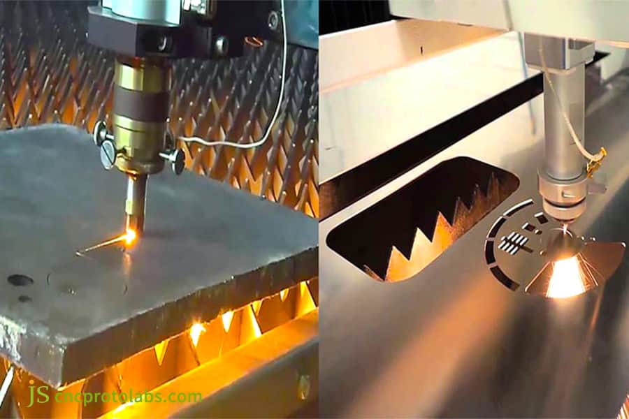
Figure 1: Fiber laser cutting 6 mm mild steel plate with oxygen assist gas.
What Is the Minimum Hole Size for Laser Cutting? (By Material & Thickness)
In laser-cut part design, the minimum hole diameter is governed mainly by how far molten spatter is thrown back during high-power piercing. In 2 mm mild steel, a 1.0T hole (2.0 mm) — and even a 0.8T hole (1.6 mm) — will hold its roundness. In 2 mm aluminum or stainless, a hole smaller than 1.2T (2.4 mm) comes out elliptical or burns through locally, because heat accumulates and slag splashes back into the hole. General rules: minimum hole diameter is 0.8–1.0T for mild steel, 1.0–1.2T for stainless, 1.2–1.5T for aluminum and 1.5–2.0T for copper. Minimum hole-to-edge distance is 1.0T for mild steel and ≥ 1.5T for everything else (≥ 2.0–2.5T for copper).
Material deformation process of laser piercing
- Pulsed piercing produces small holes that are often out-of-round or elliptical, because back-spatter of molten slag re-solidifies on the hole wall.
- In 2 mm aluminum or stainless plate, any hole below 1.2T (2.4 mm) collapses as back-spatter of molten slag re-solidifies inside it.
- Laser cutting design rules state that the distance from the hole wall to the nearest edge should be at least 1.5T, so the remaining web can carry heat away.
Safety hole diameter baseline for bolt fixing holes
- The table below gives minimum laser-cut hole diameters for M3, M4 and M5 clearance holes in 1–6 mm sheet, plus the case where drilling is the better option.
- To reduce workshop cost: For aluminum or stainless sheet thicker than 3 mm, mark the hole centres on the drawing and finish the holes on a CNC drill or machining centre.
- This prevents re-welded slag in micro-holes and cuts total piercing time by more than 20%. Minimum hole diameter in laser cutting must always be matched to plate thickness — never specify a hole size without also specifying the sheet it goes into.
Table of Minimum Hole Diameters for Common Metal Sheets and Suggested Alternatives for Mechanical Drilling
|
Material |
1 mm |
2 mm |
3 mm |
6 mm |
|---|---|---|---|---|
|
Mild Steel |
Ø0.8 / 1.5 edge / Laser OK |
Ø1.6 / 3.0 edge / Laser OK |
Ø2.4 / 4.5 edge / Laser OK |
Ø4.8 / 9.0 edge / Laser OK |
|
304 Stainless |
Ø1.0 / 1.5 edge / Laser OK |
Ø2.4 / 3.0 edge / Laser OK |
Ø3.6 / 4.5 edge / Laser OK |
Ø7.2 / 9.0 edge / Suggest drill |
|
5052 Aluminum |
Ø1.2 / 1.5 edge / Laser OK |
Ø3.0 / 3.0 edge / Suggest drill |
Ø4.5 / 4.5 edge / Suggest drill |
Ø9.0 / 9.0 edge / Suggest drill |
|
Copper |
Ø1.5 / 2.0 edge / Suggest drill |
Ø3.0 / 3.0 edge / Suggest drill |
Ø4.5 / 4.5 edge / Suggest drill |
Ø9.0 / 9.0 edge / Suggest drill |
Data: JS Precision production database, 2025, n = 8,400 parts.
For 3 mm sheet and above, treat every aluminum or stainless hole as a drilling candidate unless pierce time is explicitly costed in.
How Are Kerf Width and Edge Taper Controlled?
The focused beam of an industrial fibre laser diverges hyperbolically either side of the waist, which gives every cut a natural edge taper of 0.5° to 1.5°. Cutting 2 mm mild steel, per-side kerf allowance is set to 0.10–0.12 mm, holding tolerance within ±0.05 mm. On 6 mm aluminum the kerf widens to 0.22–0.28 mm with 0.12–0.18 mm of bottom-edge undercut. For tab-and-slot assembly, specify at least 0.20 mm of clearance on the drawing to prevent the joint jamming.
Control of the incision shape by the focal point
- Cutting with the focal point set below the sheet surface (negative focus) widens the lower kerf, which enlarges the slag-ejection channel and produces a slightly wider bottom opening.
- Because the beam keeps diverging through the sheet thickness, aluminum kerfs usually show a slightly trapezoidal cross-section. Shift the focal position to compensate.
- The digital functional model for laser cutting metal parts requires engineers to pre-calculate the kerf compensation value based on the focus mode they select.
Commonly used board cutting seam compensation for actual deviation
If a drawing calls out ±0.02 mm on a hole, laser cutting will not hold it — specify 0.3 mm of stock and finish the hole by reaming or CNC drilling instead. Re-verify cut compensation whenever you change the assist gas pressure.
Based on JS Precision's practical experience in the 2025 mold steel project, reserving a 0.3 mm allowance increases the first-pass yield of assembly from 91.4% to 99.5%.
Get a kerf-compensation check before you release the drawing. Upload your STEP or DXF file and our engineers will confirm the compensation value for your material, thickness and gas — so tab-and-slot parts assemble the first time.
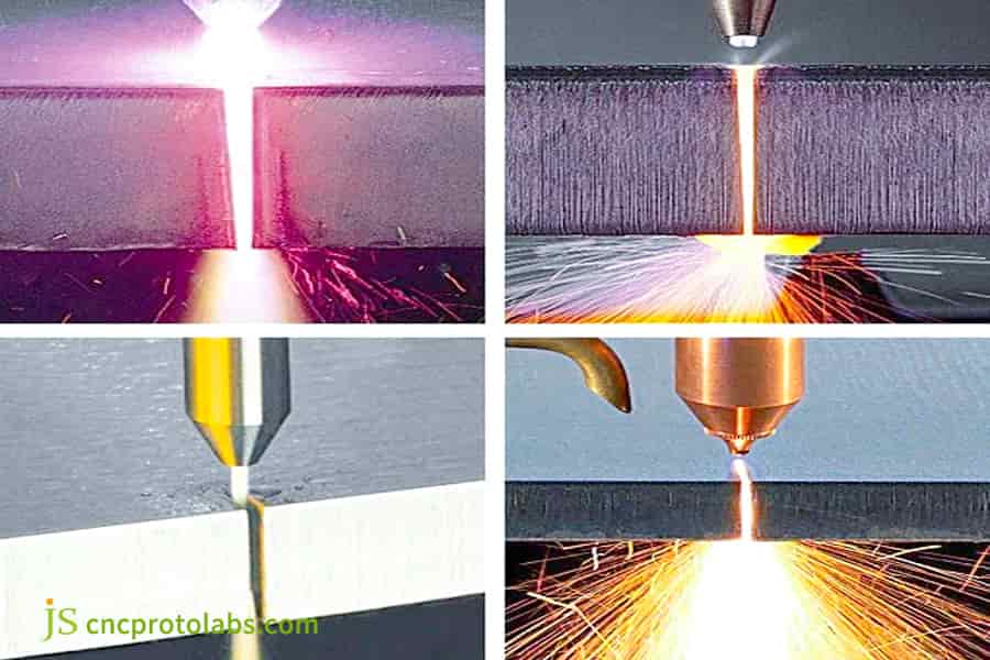
Figure 2: Close-up of laser cut kerf width and edge taper on 2 mm stainless steel.
How Do Assist Gases Lower Laser Cutting Material Selection Costs?
In laser cutting material selection, the assist gas choice directly determines edge roughness and the price you are quoted. Mild steel uses low-pressure oxygen (0.5–2.0 bar) for fast, low-cost cutting, but leaves 10–30 μm oxide scale requiring grinding. Stainless steel and aluminum require 16–22 bar of high-purity nitrogen for oxide-free, weld-ready edges — which raises gas cost to 3–5× that of oxygen. For non-cosmetic internal supports, 16 bar of clean, dry air cuts total part cost by 20–35%.
Processing boundaries of oxygen, nitrogen and air
- Oxygen best suits medium and thick carbon steel, but plates carrying heavy mill scale must be descaled first.
- High-pressure nitrogen is the right choice for parts that will be welded without post-cleaning, and for food-grade or medical enclosures, because the cut edge is bright, oxide-free metal.
- Compressed air suits galvanized steel and general equipment enclosures. For stainless steel, choose the gas by what happens after cutting: nitrogen if the part will be welded or powder-coated, air only if a light oxide is acceptable.
Drawing grading and premium elimination
- Engineers shall specify on the drawings that an internal frame can be shipped by high-pressure air cutting, while cosmetic or exterior panels must be cut with high-pressure nitrogen to prevent oxidation.
- This also lets your procurement team strip out gas premiums that buy nothing, and lowers unit cost.
- Assist gas can account for up to 30% of a laser cutting quote. Tiering the gas specification by part function is the fastest way to cut that line item.
Comparison of Laser Cutting Assist Gas Selection and Cost
|
Gas Type |
Applicable Metal |
Edge State (Oxide/Ra) |
Post‑treatment Compatibility |
Relative Cost Index (O2=1.0) |
|---|---|---|---|---|
|
Oxygen |
Mild steel |
Oxide 10–30 μm / Ra 6.3–12.5 |
Requires grinding before coating |
1.0 |
|
High‑purity N2 |
Stainless, Aluminum |
Oxide‑free / Ra ≤ 3.2 μm |
Direct welding, no grinding |
3.0–5.0 |
|
Compressed Air |
Galvanized, Internal |
Light oxide / Ra ≤ 6.3 μm |
Acceptable for internal parts |
1.5–2.0 |
Surface quality after thermal cutting is graded per ISO 9013, and general dimensional tolerances for sheet-metal parts follow ISO 2768-m unless the drawing states otherwise.
Gas is the only line item in this table you can negotiate without changing the part — tier it by part function.
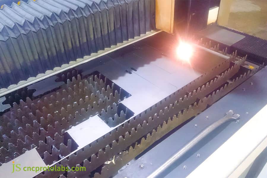
Figure 3: High-pressure nitrogen laser cutting of 5052 aluminium sheet.
How to Prevent Corner Burnout and Tip Collisions?
When the laser head cuts acute angles (< 90°) at high feed rates, the CNC axes decelerate and energy concentrates, causing corner burnout and dimensional deviation. For ≥ 3 mm mild steel or stainless structures, CAD should change sharp internal corners to R ≥ 0.5T micro-radius, or let the CAM programmer add an external loop (lead-out) that gives the corner time to cool. Additionally, thin parts can tip up during cutting; aluminum nesting requires 0.8–1.2 mm micro-tabs, stainless steel 0.4–0.6 mm to prevent head collision.
CNC machine tool feed heat accumulation effect
- Burned corners opened chassis joint gaps from 0.5 mm to more than 1.5 mm, which broke the IP54/IP65 seal.
- When the machine decelerates into an acute corner, feed rate drops sharply, energy concentrates, and the corner over-melts.
- For custom laser cutting service, optimise the toolpath in CAM so heat is spread across the sheet instead of piling up in one corner.
micro-tab point nested layout setting principles
- If the tabs are too large, they leave visible marks even after manual deburring; if they are too small, the part breaks free during cutting, tips up, and can crash the cutting head.
- Use 0.8–1.2 mm micro-tabs on 3 mm aluminum and 0.4–0.6 mm on 3 mm stainless steel. On thinner sheet, scale the tab down proportionally — a tab that is too wide will not break cleanly by hand.
- Micro-tab sizing and corner radii (R ≥ 0.5T) are both necessary to avoid corner burn-through.
In 8,400 parts cut at JS Precision in 2025, switching from continuous to leapfrog cutting on 3 mm 5052 aluminum cut the flatness rejection rate from 11.3% to 0.8%.
Still fighting corner burn-through? Send us the drawing and we will return the corner radii and micro-tab layout we would run.
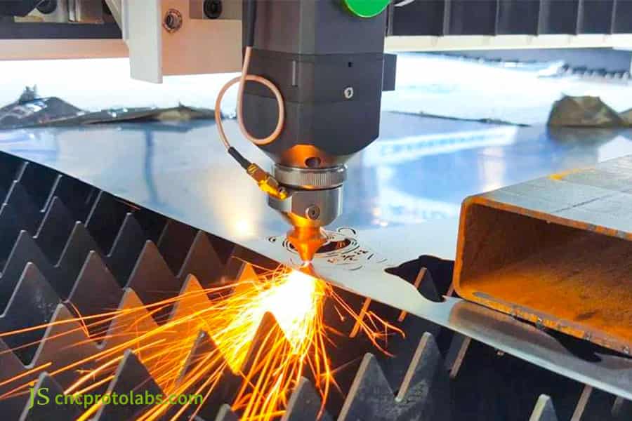
Figure 4: Laser cutting metal part near tube component.
How to Stop Cut Hardening from Ruining Bending and Tapping?
Laser cutting leaves a 0.1–0.3 mm hardened, martensitic layer inside the heat-affected zone (HAZ) at the cut edge. For carbon steel, tapping straight into a laser-cut edge raises tap breakage by more than 50%. Separately, when the hole-to-bend-line distance drops below 2.5T + R, bending strain stretches a round hole into an oval and the bolt will no longer pass through. To prevent this, reserve L ≥ 2.5T + R, or pre-cut bend relief slots. For ≥ 3 mm structural plates, drill pilot holes or use PEM nuts instead of tapping.
Material cutting, bending and tapping process chain
- Rapid heating and cooling hardens the cut edge. In JS Precision's 2025 data, that raised tap breakage and jamming rates by more than 50% versus a machined edge.
- Too little distance between the hole and the bend line means bending strain stretches the round hole into an oval.
- Laser cutting metal parts must be designed with subsequent bending and tapping in mind, because a laser-cut edge behaves very differently from a machined one.
Hole edge deformation prevention safety distance and relief slot
Formula for the hole-to-bend safety distance:
L ≥ 2.5T + R
Where L = distance from the hole edge to the bend line, T = sheet thickness, and R = inside bend radius. Use this on every hole that sits within 10T of a bend.
If the layout is too tight to allow that distance, add a narrow pre-cut relief slot. Size it at 1.0–2.0 mm wide (see the table below) and run it past the bend line, so it relieves strain without creating a stress riser.
Specifications for Hole Edge Deformation Prevention Safety Distance, Relief Slot, and Thread Treatment
|
Thickness |
Min Hole‑to‑Bend Distance (2.5T+R) |
Relief Slot Width/Depth |
M3–M8 Thread Treatment |
|---|---|---|---|
|
1.5 mm |
4.55 mm (T=1.5, R=0.8) |
1.0 / 3.0 mm |
Laser pilot + drill tap |
|
2.0 mm |
5.80 mm (T=2.0, R=0.8) |
1.2 / 4.0 mm |
Laser pilot + drill tap |
|
3.0 mm |
8.55 mm (T=3.0, R=1.05) |
1.5 / 5.0 mm |
PEM nut or pilot + tap |
|
4.0 mm |
11.30 mm (T=4.0, R=1.3) |
2.0 / 6.0 mm |
PEM nut recommended |
Data: JS Precision production database, 2025, n = 8,400 parts.
These distances assume a standard V-die. On tight-radius dies, add 0.5T.
Broken taps and oval holes cost more than the part. Get a threading and bend-relief review, with PEM or rivet-nut alternatives priced side by side.
Case Study: How JS Precision Eliminated Warpage on Al 5052 Inverter Cases?
JS Precision delivered a warpage-free solution for 5052 aluminum inverter cases through precision laser cutting service, optimizing DFM and cutting parameters.
Difficulties encountered by customers
- The chassis was 3.0 mm 5052 aluminum, with 180 closely spaced heat-dissipation louvers across the top face at a pitch of only 3.0 mm — 1.0T, well below the 1.5–2.0T we recommend for aluminum.
- Heat accumulation arched the whole blank by more than 6.5 mm — far beyond the ≤ 0.8 mm flatness the drawing called for.
- Custom laser cutting service needed a way to control heat accumulation and slag removal. Without a fix, the part could not move into production.
JS Precision Solution
- DFM tuning increased the louver pitch from 3.0 mm to 4.35 mm (1.45T spacing) and replaced every sharp corner with a 1.0 mm radius.
- Skip-step (leapfrog) cutting. In CAM, we replaced continuous unidirectional slotting with a symmetric outside-in sequence, so no two adjacent louvers are cut back-to-back and each one has about 1 s to shed heat before its neighbour is cut.
- Ultra-high-pressure nitrogen. We raised nitrogen pressure from 13 bar to 18.5 bar and switched to a 2.5 mm coaxial double-layer nozzle. The higher kinetic energy blows molten metal out of the kerf before it can re-solidify, so no slag builds up.
Failure experience and lessons learned
During trial cuts we raised the feed rate by 25% to cut heat input. It backfired: the molten aluminum solidified in the kerf, the cut failed to break through, and back-spatter travelled up into the nozzle and contaminated the protective window.
The lesson: on aluminum sheet, thermal control comes from balancing heat input against a high-velocity gas jet — not from feed rate alone.
Final result
- Finished panel flatness held within 0.45 mm across the batch — well inside the customer's 0.8 mm requirement — and the cut edges went straight to powder coating without sanding.
- First-article inspection pass rate reached 99.2%, unit cost fell 22% against the original process, and assembly time for the first 500-unit batch dropped by 12 days.
Data source: JS Precision quality delivery file, batch #INV-AL5052-202511. Full inspection report and flatness measurement sheet available on request.
Want to see more practical case studies on preventing aluminum sheet warping? View the detailed process review now, replicate successful experiences, and ensure your material cutting passes inspection on the first try!
FAQs
Q1: Why is oxygen commonly used for mild steel but high-pressure nitrogen for stainless steel?
Mild steel is cut with oxygen because the iron–oxygen exothermic reaction supplies roughly 60% of the cutting energy, which lets a lower-power laser handle medium-thick plate. Stainless steel behaves the opposite way: its chromium and nickel form a dark chromium-oxide layer the instant oxygen is used, and that layer must be ground off before welding. So instead, high-pressure nitrogen simply melts the metal and blows the slag out, giving a bright, oxide-free edge.
Q2: What causes heavy bottom dross when laser cutting aluminum sheet metal?
Aluminum alloys conduct heat well and their melt is highly viscous. If nitrogen pressure or purity is too low, or the nozzle is worn, the molten metal is not expelled cleanly and re-solidifies as hard dross on the underside of the sheet. Raise nitrogen pressure to 16–20 bar and switch to a double-layer coaxial nozzle to get a smooth, dross-free cut.
Q3: Can a fiber laser machine cut precise countersink screw holes directly?
No — not to a usable tolerance. A laser cuts vertically, so it cannot produce a true countersink. The standard route is to laser-cut the through-hole and then machine the countersink with a countersink cutter on a drill press or CNC; the alternative is to press in a rivet nut after cutting. Tilting the cutting head gives poor accuracy and risks damaging the protective lens.
Q4: What dimensional tolerances can be reliably held in sheet metal laser cutting?
Expect ±0.05 to ±0.10 mm on carbon and stainless steel up to 3 mm thick, and about ±0.15 mm in the 5–10 mm range. Unless the drawing states otherwise, general tolerances follow ISO 2768-m. That is tight enough for chassis and cabinet assemblies, and profiles are cut 3–10× faster than by CNC milling.
Q5: Why do manufacturing engineers recommend enlarging the hole-to-edge distance before fabrication?
When a hole sits too close to the edge, the narrow web between them overheats. The result is localised burn-through, melting, bending or tearing — especially in thin-wall parts. Keep the web at least 1.5T wide (2.0–2.5T for copper) so heat has a path out and the hole stays round and in position.
Q6: How can parts be nested and designed to reduce laser subcontracting costs by 20%?
Yes — 20–35% is realistic, and it comes from three levers.
- Common-line cutting: merge adjacent straight edges so the laser traverses each line once instead of twice, which typically shortens the cutting path by up to 30%.
- Pierce-count reduction: replace small holes with laser-marked centres and drill them offline, since every pierce costs both time and gas.
- Gas tiering: cut non-cosmetic parts with high-pressure air instead of high-purity nitrogen. Part count per sheet (nesting utilisation) is the fourth lever and usually the biggest one of all.
Q7: What production capabilities does JS Precision use to control quality on multi-material laser parts?
JS Precision runs a high-power fiber laser cell, a precision bending centre and an in-house coating line, backed by a parameter library covering 200+ material/thickness combinations. Within 2 hours the team returns a thermal-distortion warning and a DFM diagnosis for your drawing, and every batch ships with a Zeiss CMM full-dimension inspection report under our ISO 9001 quality system.
Q8: Which primary design factors dictate the quoting price of a Metal Laser Cutting Service?
A laser cutting quote is driven by five factors: material weight, sheet utilisation, pierce count, total cut length, and assist gas. Pierce count is the hidden one — every pierce time and gas, so a light part with 500 small holes can easily cost more than a heavy part with 20.
Summary
Design for manufacturability (DFM) in sheet metal is a practical engineering discipline that deals with material properties, thermal deformation, and toolpaths. Carbon steel needs oxygen-managed, burn-resistant corners. Stainless steel needs web spacing wide enough to let heat escape. Aluminum needs high-pressure slag removal and controlled piercing. In every case, a dimension of a few tenths of a millimetre on the drawing decides yield and cost. By standardizing hole diameters, wall thicknesses, and bending interference parameters, designers can avoid repeated modifications and delays, and manufacture precise and economical components.
Send your 3D CAD (STEP) or 2D (DXF/DWG) drawings to the JS Precision engineering team now to get a free DFM review and manufacturing quote. You get a DFM report that flags every at-risk feature before the first cut, so the part reaches production without a second toolpath.

Disclaimer
The contents of this page are for informational purposes only. For JS Precision Services, there are no representations or warranties, express or implied, as to the accuracy, completeness, or validity of the information. It is the buyer's responsibility to identify specific technical requirements and request a formal parts quotation. Please contact us for more information.
Resource

