 English



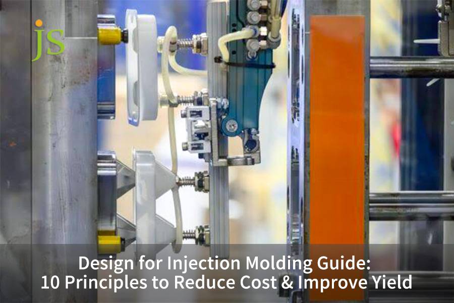

Design for injection molding refers in particular to methods of engineering that help achieve the reduction of mold costs, elimination of defects and optimization of per-part pricing in custom plastic manufacturing. When engineers implement ≤±10% DFM concepts which consist of, for example, wall thickness tolerance 10%, increase of draft angle by 1° in case of 0.025 mm depth of texture, and gate location, the result is a 30% reduction in cycle time and yield increase beyond 98.5% of output. Checking DFM factors before steel cutting prevents costly mold changes and eliminates secondary machining operations.
Overview of 10 Principles of DFM Injection Molding Service
|
DFM Principle |
Technical Limit |
Cost & Yield Impact |
Target Benefit |
|---|---|---|---|
|
Wall thickness uniformity |
Fluctuation ≤ ±10% nominal |
Eliminates sink marks & warp |
Reduces cycle time 15–25% |
|
Draft angle matching |
Base 0.5°–1.5°, +1° per 0.025 mm texture |
Prevents drag & scuff |
Lowers reject rate to <1.5% |
|
Rib & boss ratio |
Rib thickness = 40–60% base wall |
Avoids opposite sink mark |
Maintains strength without added material |
|
Internal radius |
R ≥ 0.5 × local wall thickness |
Reduces stress concentration |
Extends mold life to 500k+ shots |
|
Undercut elimination |
Pass‑through with 5° shut‑off or bump‑off |
Removes side‑action slides |
Cuts mold cost 20–35% |
|
Gate placement & type |
Sub‑gate or valve gate at thickest section |
Boosts weld line strength 30%+ |
Eliminates manual degating |
|
Conformal cooling |
Channel distance = 1.5–2.0 × diameter |
Controls core temperature ±1.5℃ |
Prevents thermal distortion |
|
Tolerance allocation |
ISO 20457 Grade 7, anisotropic shrinkage accounted |
Avoids blind tight tolerances |
Reduces mold rework cost |
|
Surface finish selection |
SPI C1–D3 matte for non‑cosmetic parts |
Avoids expensive A1 mirror polish |
Saves 30% polishing cost |
|
Steel‑safe dimensioning |
Leave stock on critical features |
T1 adjustment via EDM only |
Achieves batch yield 99.2% |
Key Takeaways
- Principle Compliance: In line with strict compliance to the 10 main Direct-to-Manufacturing (DFM) principles, the production defect rate of injection molded parts can be brought down to less than 0.8%.
- Demolding & Surface Optimization: By using SPI/VDI surface roughness standards to determine draft angles, drag mark, ejection damages can be avoided.
- Mold Cost Efficiency: By replacing side-action cores and improving gate design, up to 35% can be saved during the first mold tooling costs.
- Engineering Implementation: Working with JS Precision on a DFM comprehensive review before the design of the model allows the fixing of machining tolerances at the stage of ±0.05 mm as well as cost reductions per item.
Why Trust JS Precision’s DFM Services?
Successful implementation of design for injection molding depends on how thoroughly an engineer understands material shrinkage, mold thermal balance, and injection molding process.
We can take this gear as our team's sample work: a PA66+30%GF injection-molded gear supplied directly by the client. The predecessor supplier reached 0.12mm coaxiality (when the requirement was just 0.03mm), had prominent sink marks in their gear root areas, and a defect rate of 18.5%.
Thanks to three months of DFM improvements, thinning down the webs from 3.5mm to 2.2mm, incorporating four symmetrical gussets, and adding 3D-printed cooling channels, we brought coaxiality to a stable 0.022mm, decreased the molding cycle time from 42 seconds to 28 seconds, and increased the yield rate to 99.4%.
ISO 9001:2015 is clear: Process parameters (temperature pressure cycle time) have to be recorded, controlled, and monitored to ensure the quality of the product is always the same. Complying with these quality management standards is very strict.
To meet ISO 9001:2015, JS Precision has made mandatory this three elements for each DFM injection molding service: Statistical Process Control (SPC) monitoring of process parameters, complete preventive maintenance records for each mold, and a three-step Zeiss CMM inspection covering first sample parts, in-process, and finally finished inspections. A Cpk process capability analysis report is attached to each batch of injection molded parts manufacturing .
Want to master the core methods of DFM (Design for Manufacturing) for injection molding? Download JS Precision's Injection Molding DFM Design White Paper now. It will help you mitigate 80% of mold modification risks during the CAD phase.
How Does Uniform Wall Thickness Control Reduce Warpage and Sink Marks in Injection Molding? (Principle 1)
The basic rule governing design for injection molding is to ensure thickness fluctuations are not more than ±10%. At JS Precision, a 3:1 gradual chamfer design has been used in melting channel shaping optimization, and defect rates were maintained below 0.5%.
Material Shrinkage Rate Differences
- Crystalline plastics (e.g., PA66): Shrinkage rate of 1.5%-2.5%, prone to non-linear shrinkage when wall thickness is uneven.
- Amorphous plastics (e.g., PC): Shrinkage rate of 0.5%-0.7%, less sensitive to wall thickness variations.
- Cooling time formula: tc ∝ T², doubling the wall thickness quadruples the cooling time.
Manufacturer Services
- Moldflow Simulation: When carrying out plastic injection molding service, JS Precision uses Moldflow software to discover hot spots and offers 3:1 geometric transition solutions.
- Gradual Chamfer Design: A 3:1 gradual chamfer is employed at the points of sudden wall thickness change to facilitate a smooth melt flow transition, which can avoid turbulence and air pocket formation.
- High Yield Manufacturing: These processes result in keeping the defect rate of the high-yield injection batch down to 0.5%.
In a nutshell, having the same wall thickness all over the part is equivalent to having a water pipe of constant diameter, the water flow remains even. But when the pipe suddenly goes narrower, the pressure increases causing the sink or warp mark on the plastic part.
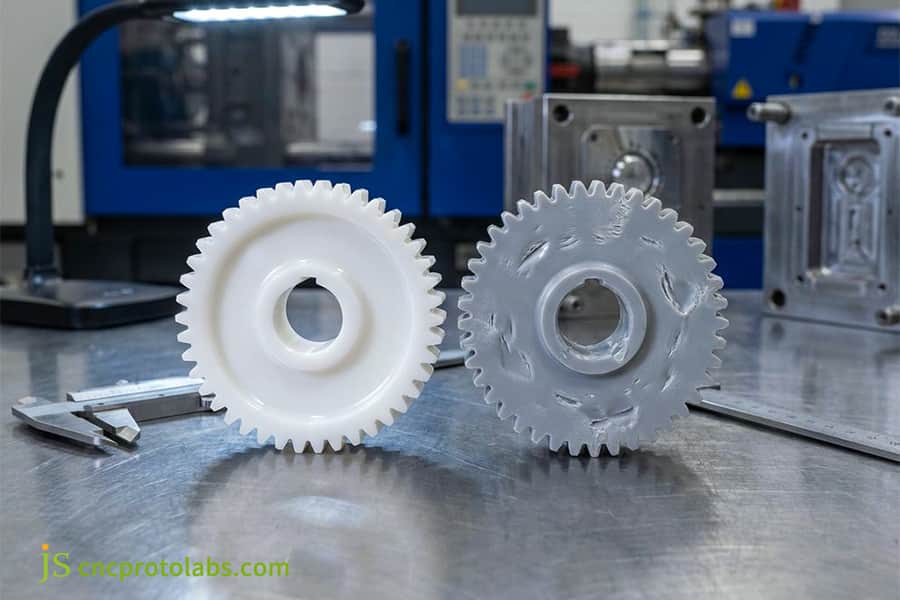
Figure 1: White plastic gears and measuring tools in injection molding factory.
What Draft Angle Standards Prevent Surface Scuffing for SPI and VDI Mold Textures? (Principle 2)
Draft angles must be matched accurately with surface roughness based on the injection molding DFM guide. Polished parts with surface roughness SPI A2 need only 0.5°-1° draft angle but for deep-textured surfaces like VDI 30, the draft angle increases by 1° per 0.025mm depth of texture so that no surface scuffing takes place.
SPI Polish Grade vs. Draft Angle Mapping
| SPI Grade | Surface Description | Recommended Draft Angle |
| A1–A3 | Mirror polish | 0.5°–1° |
| B1–C3 | Grinding / matte | 1°–1.5° |
| D1–D3 | Sandblast / texture | 1.5°–2° |
VDI Texture Grade vs. Draft Angle Mapping
- VDI 12-24 (Fine texture): Recommended 1.5°-2°.
- VDI 27-36 (Heavy texture): Recommended 2.5°-5°.
- Deep cavity rule: If the depth of a cavity's wall exceeds 50mm, you will be required to draft an additional 0.5° for every additional 25mm in depth.
Putting It into practice
JS Precision's custom injection molding service include draft angels calculation, based on SPI/VDI rating, automatically done by system to prevent parts damaging or scuffing during ejection and maintain the batch scrap rate under 1.5%.
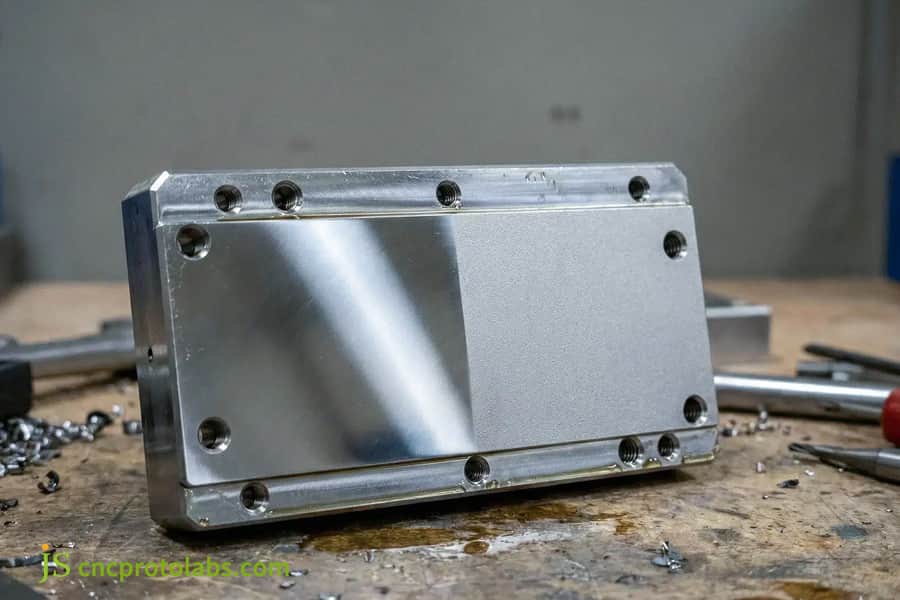
Figure 2: CNC machined aluminum mold base with precision holes.
How Should Ribs and Bosses Be Designed to Optimize Structural Integrity Without Cosmetic Defect? (Principle 3)
The base thickness of a rib in design for injection molding is usually taken as 40%-60% of the outer thickness of the wall, a small fillet at the base of a boss of 0.25, the opposite surface and also increase the shear strength
Rib Geometric Proportions
- Thickness: The rib thickness = 0.5×T (Thickness of the main wall), with a maximum of 0.6T.
- Height: ≤3T to overcome molding issues of filling.
- Draft angle: 0.5°-1° to make ejection easy.
- Base fillet: R = 0.25T to relieve stress concentration.
Key Features to Take Care while Designing the Screw Boss
- Outer Diameter: It is important that it be twice the inner diameter to have enough wall thickness for adequate structural support.
- Base Gussets: Placed every 45° for maximum improvement of flexural rigidity.
- Air Vents: To let off trapped air from deep boss features, air vents are to be made on top of the bosses.
Through these optimizations, the injection molding cost reduction effect is significant: the material usage is reduced by 15%, the molding cycle is shortened by 10%, and there is no need for subsequent repairs.
Unsure if your part's injection molding cost is reasonable? Contact JS Precision engineers, simply provide the material type and annual production volume to receive an accurate per-unit cost estimate within 30 minutes,rapid assessment is possible even without technical drawings.
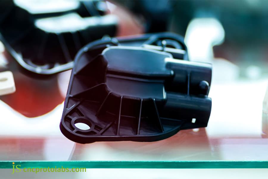
Figure 3: Black plastic injection molded products on display.
Why Is Internal Radius Optimization Critical to Minimize Stress Concentration and Fracture? (Principle 4)
The injection molding DFM guide emphasizes that maintaining a corner inner corner radius R ≥ 0.5 x wall thickness can reduce the stress concentration factor from 3.0 to below 1.5, effectively preventing drop cracking and extending the service life of the mold.
Stress Concentration Factor (Kt) Fluctuations
- R/T < 0.4: Stress concentration is very steep, risk of part cracking goes up by 60%.
- R/T 0.5-0.6: The spread of stress is more uniform, Kt drops under 1.5.
- R/T > 0.6: Getting less benefit for each reduction whereas the use of material increases.
Matching Formula for Inner and Outer Corner Radii
R_out = R_in + T (Outer Radius = Inner Radius + Wall Thickness)
This ensures constant wall thickness at corners, avoiding heat accumulation and sink marks.
JS Precision, a mold manufacturer, inspects the R/T ratio of internal corners regularly during high-yield injection manufacturing, which is how they became able to completely prevent stress issues that could damage the parts. Their customers rarely if ever get complaints about breakage or cracking after that.
How Can Undercuts Be Re-Engineered to Eliminate Expensive Side-Action Mold Sliders? (Principle 5)
The key technique for injection molding cost reduction is to use pass through or bump off design, which can eliminate lateral sliders while ensuring functionality, directly reducing mold opening costs by 20% -35%.
Drawbacks and Costs of a Regular Slider
- Larger mold area: The total space required by the mold becomes larger due to the addition of the Slider mechanisms and this further results in increase of steel costs.
- Slider movements length injection cycles: Slider movements add around 5%-60% to the time of each cycle.
- Chance of flashing: Flash very often appears at the place of contact between two cavities/partinglines of mold and additional deburraing work is carried out.
Pass-Through Design
- 5° degrees shut-off angle: With the lock mechanism of the two halves, the moving and the fixed mold, the undercut molding is obtained besides, the mold cost introduction is not necessary.
- Preferred uses: open undercut features (like side holes/side slots).
Bump-Off (Forced Ejection)
- Material elasticity requirements: Suitable for materials having more than 10% elongation like PP and PE.
- Depth restriction of undercut: Depth of undercut ≤ 5% of wall thickness.
- Leading chamfer at ejection edge: A leading chamfer of 30°-45° degrees is used at the ejection edge.
At JS Precision, through the DFM injection molding service we identify the undercuts at the CAD stage, and then recommend the most favorable changes to redesign, enabling the customers to avoid mold cost and mold investment costs too.
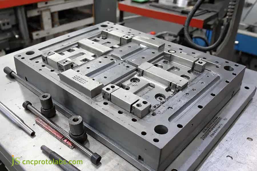
Figure 4: Complex steel injection mold tooling components.
How Do Gate Placement and Type Affect Weld Line Integrity and Surface Cosmetics? (Principle 6)
In injection molded parts manufacturing, gate location determines molecular chain orientation and packing efficiency. Placing the gate at the thickest cross-section ensures smooth filling, while using submarine gates or valve-gated hot runners, positioned away from visible surfaces ,can increase weld line strength by over 30%.
Fundamental difference between weld lines and meld lines
- Weld Line: Two melting fronts meet together, molecular chains cannot entangle perfectly here, and so this area has a strength reduction of 20%-40%.
- Meld Line: Molten materials are merged at a higher temperature, more molecular chains become entangled and the strength loss will be less.
Gate type selection
| Gate Type | Advantage | Disadvantage |
| Edge gate | Simple, low cost | Requires manual trimming, visible mark |
| Submarine gate | Automatic degating, hidden mark | Requires specific material flow characteristics |
| Valve gate | Precise filling control, no cold slug | Higher cost |
Manufacturer optimization practice
JS Precision optimized the shrinkage path during the packing phase through Moldflow analysis, moving the fusion line area to the low stress zone and increasing the forming yield of high-yield injection manufacturing to over 99%.
Concerned that weld line strength might affect part performance? Submit your part drawings, and JS Precision will provide a free Moldflow gate location analysis report to pinpoint the optimal injection strategy, ensuring weld line strength increases by more than 30%.
How Does Cooling Channel Design Reduce Cycle Time and Prevent Thermal Deformation? (Principle 7)
In plastic injection molding service, the cooling phase is responsible for 60-70% of the total cycle time. Keeping 1.5-2.0 times the channel diameter as a distance between cooling channels and cavity wall or using conformal cooling channels will help control mold surface temperature variation within ±2℃, thereby allowing a reduction in cycle times by over 20%.
Conventional Cooling Channels vs. Conformal Cooling Channels
|
Cooling Method |
Temperature Difference |
Cycle Time Impact |
|---|---|---|
|
Straight drilled channels |
±10 °C |
Baseline |
|
Conformal cooling (3D printed) |
±2 °C |
–20% to –30% |
High-Thermal-Conductivity Inserts
- Beryllium Copper: Thermal conductivity about 3 times higher than mold steel, suitable for deep cavities.
- Control of the Difference between Core and Surface Temperatures: Difference has been reduced from ±10℃ to ±2℃, removing heat release roadblocks.
JS Precision reduced the processing time of a single piece by 22% in the injection molding cost reduction project through a conformal waterway design, while eliminating warping and scrap caused by uneven cooling.
How Does Tolerance Allocation and Resin Shrinkage Matching Ensure High-Yield Production? (Principle 8)
High-yield injection manufacturing largely depends on logical specification of tolerances.In JS Precision, they are able to greatly reduce debugging expenses and the rate of scrapping by enlarging non-mating dimensions only to the extent of ISO 20457 Grade 7 and carefully tailoring mold cavities as the anisotropic shrinkage of the resin materials.
Tolerance Standard Grades
- ISO 20457 / DIN 16901: Standards of dimension tolerances exactly for engineering plastics which classify non-critical and tightly fitting dimensions.
ISO 20457:2018 specifies that process induced deviations can be reduced by effectively designing plastic molded parts and optimizing production processes when specifying manufacturing tolerances for plastic molded parts.
JS Precision has relaxed the non fitting dimensions to level 7 based on this, and fine tuned the mold cavity with a difference of 0.3%-0.8% in the flow direction and 0.7% -1.2% in the vertical direction of PA66+30% GF to avoid blind tight tolerances.
- Non-critical Dimension: Tolerances are loosened to Grade 7 not to over-specify tight tolerances indiscriminately.
- Tightly fitting Dimensions: Room for the correction of deviation from dimensions was based on shrinkage anisotropy.
Anisotropic Shrinkage Data (Example: 30% GF PA66)
- Flow Direction: Shrinkage rate approx. 0.3%-0.8%.
- Cross-Flow Direction: Shrinkage rate approx. 0.7%-1.2%.
Steel-Safe Strategy
JS Precision uses the steel-safe design strategy to manufacture their molds for high-precision dimensioning by deliberately retaining some extra material for future trimming. Once they get the measurement results from the T1 trial shot, they then go for EDM precision machining to make the last adjustments that secure mass-production yields in excess of 99%. And this is one of the highlights of the custom injection molding service.
Ready to move your project forward? Submit your 3D CAD drawings and tolerance specifications, and JS Precision will provide a free DFM assessment and a competitive quote within 24 hours. We ensure high yields right from the design stage, setting you up for successful mass production from the start.
How Does Surface Finish Selection Impact Tooling Costs and Secondary Polishing Overhead? (Principle 9)
Excessive labeling of mirror polishing in injection molding cost reduction can lead to a significant increase in mold working hours. By appropriately choosing SPI/VDI grades or matte finishes according to functional needs, savings of up to 30% can be achieved for machining costs without loss of the intended visual appeal.
SPI Polishing Cost Tiers
|
SPI Grade |
Process |
Relative Cost |
|---|---|---|
|
A1 (Mirror) |
Diamond paste multiple steps |
5× baseline |
|
B1 (Grinding) |
Fine stone + paper |
2× baseline |
|
C1–D3 (Matte / Texture) |
Sandblast / EDM texture |
1× baseline |
The Hidden Value of Texture
Using matte finishes or light texture is a common and effective approach to conceal cosmetic injection molding defects (for example, minor sink marks or flow lines), and lowering scrap levels caused by imperfection in the appearance of parts.
JS Precision provides the most cost-effective mold surface treatment recommendations based on the component assembly environment (internal structural components vs. external appearance components), helping customers achieve a balance between cost and quality in plastic injection molding service.
How Does Steel-Safe Dimensioning during Mold Machining Protect Against Material Shrinkage Risks? (Principle 10)
High-yield injection manufacturing's very last line of defense: machining the molding tool with a Steel-Safe philosophy not only leaves room for tolerance adjustment after the trial, it can be achieved just by eliminating metal. The welding risks and material build-up expenses are entirely avoided by this approach.
The Geometer's Allowance Logic
- Dimensions that are enclosed (for example, hole diameters or internal cavities): Make sure the molded steel is undersized during machining (i.e. There is additional steel/less material is removed).
- Enclosed dimensions (for example, outer diameters or bosses): Mold steel is machine to be oversized (extra steel is left/less material is cut).
Precision Mold Modification Loop
- CMM Measuring of the First-Article: Dimensional check after the T1 mold trial.
- EDM or CNC micro adjustments: Based on measurement data, extra steel is stripped away, so the dimensions are once more within specification.
- Batch verification: The first-pass yield must be over 99.2%.
JS Precision, through their use of the Steel-Safe strategy in injection molded parts manufacturing, is able to reduce the amount of times one has to go back and rework of the mold from industry norms of 3-5 to merely 1-2, That's why, Greatly cutting down on lead time.
JS Precision Custom Injection Molding Service Case Study Precision Nylon Gear Yield Optimization
Through systematic DFM analysis, JS Precision increased the yield of precision dual-layer gears (PA66 + 30% GF) from 81.5% to 99.4%.
Challenges Faced by the Customer
A client specializing in automation equipment faced problems with PA66 + 30% GF precision duplex tooth wheels: coaxiality was off limits (≤ 0.03mm requirement vs. 0.12mm by the previous supplier), there were sinkmarks on the gearbase root areas, weld lines were cracked and the breakage rate was 18.5%.
JS Precision Solutions
- Wall thicknesses and rib design (Concepts 1 & 3): Thinning the webs down to 2.2mm and providing for four identical gussets on the parts.
- Gate changes (Rule 6): Going from a single-entry side gate to a 3-point valve-gate hot runner set-up with diaphragm gate.
- Conformal cooling (Concept 7): We carried out cooling temperature control via 3D-printed conformal cooling channels that kept variation within ±1.5℃.
Lessons Learned
The first trial of T1 molding neglected the effect of PA66's very strong water absorption on the size reduction post-molding, the parts looked all right after drying but then they didn't satisfy the tolerance after being stored for 48 hours. Afterwards, the team developed the Post-Shrink and Dimensional Variation Compensation Database after Conditioning Treatment and adjusted the steel corrective values for the mold cavities again (Principle 10).
Final Results
The finished product's concentricity was continuously at 0.022mm, the tooth root shear strength was 45 % higher, the molding cycle was shortened from 42 sec down to 28 sec, and the initial batch rate was 99.4%.
Looking for the same precision gear injection molding solution? Contact the JS Precision engineering team today for a customized proposal and quote, we will replicate this success,achieving a 99.4% yield,tailored to your specific part requirements.
Why Choose JS Precision as Your Trusted Custom Injection Molding Service Partner?
Being a company with 15 years of specialization in precision injection molding and with facilities housing high-precision CNC workshops and CMMs, JS Precision delivers a fast-tracking, one-shot, custom injection-moulding service for a global clientele.
- Machining Accuracy: Mold steel component machining can achieve a ±0.005mm accuracy with full dimensional measurement performed by a coordinate measuring machine (CMM).
- System Certification: The factory is ISO 9001:2015 certified so that any material will be traceable.
- Mold Offerings: From rapid prototyping molds (Rapid Tooling) to high-durability production toolings that can run through hundreds of thousands of production cycles - we've got your back.
- Cost and Technical Responsiveness: A complete package of DFM evaluation reports and pricing is submitted within 24 hours to avoid the costs of redesign.
When it comes down to the choice of an injection molding service, JS Precision's direct production model closes the loop: DFM, mold making, injection molding, inspection all in one, ensuring top-notch control over both delivery times and product quality.
FAQs
Q1: What is the primary purpose of Design for Injection Molding in custom plastic manufacturing?
The use of injection molding DFM, in effect, is to optimize and reshape component geometry. This can cause smooth melt filling without damage to the ejection phase. Through standardization of wall thickness, and draft angles it is possible to eliminate defects such as sink markings and warpage. The process can also help to reduce mold modification and costs, and speed up the cycle time.
Q2: How does JS Precision ensure high yield and tight tolerances for complex injection molded parts?
JS Precision takes Moldflow to simulate filling, complemented with high-accuracy CNC mold (±0.005mm) production and conformal cooling channels. It is the whole range of the CMM that is put to work for critical tolerances to be achieved at ±0.05mm level without affecting the production run of over 99%.
Q3: How do I get an accurate cost quote for custom injection molding services?
If you send us your 3D CAD (STEP files), material requirements, roughness (in SPI/VDI scale), and projected volume, JS Precision will give you a breakdown between mold costs and per-part production times in a fully understandable manner.
Q4: What is the ideal wall thickness range for engineering plastics in injection molding?
One to three millimeters of a wall thickness is the nominal wall thickness. It is guaranteed that the wall is of the same thickness everywhere. The local cross section changes must stay within ±10% tolerance. Sudden changes from thin to thick in walls can create non-uniform shrinkage, voids in the materials and lengthen injection molding operations.
Q5: Why is draft angle essential for custom injection molded part features?
Draft angles remove friction during ejection between the part and the cavity walls. Usually, a draft of 1 degree to 2 degrees is needed, if for textured materials an extra 1 degree of release is required for every layer of 0.025mm to avoid surface abrasion and parts damage while ejection.
Q6: How does gate selection influence manufacturing costs and component structural strength?
The choice of gate affects the molecular chain orientation and degree of packing. The installation of submarine gates or hot runner systems can save the human working time spent on manual trimming of gates. If the gate is placed on a thicker wall section, apart from avoiding sink marks it also weld lines are away from stress areas, which leads to strength by 30% increase.
Q7: Can modifying part design eliminate expensive side-actions and mold sliders?
Redesigning undercuts by CAD to pass-through features (with 5° shut-off faces) or bump-off features would get you out of having any further need for side-action slider mechanisms and directly reduce mold manufacturing costs by 20-35% and cycle time as well.
Q8: What materials offer the best cost-to-performance ratio for structural injection molded parts?
PP or PE is the most favored selection for general structural parts. When there is a need for high load-bearing as well as temperature resistance, one among ABS, PC, or high strength and flame-resistant material like PA66+30%GF which has best cost-effectiveness among similar products can be chosen.
Summary
Following the 10 DFM principles is the cornerstone of cost reduction and quality improvement. Implementing key design criteria during the CAD phase can reduce mold modification risks, achieve high yield mass production, and enhance product competitiveness.
Are you looking for a reliable injection molding manufacturer to bring your engineering project to life? JS Precision is ready to provide comprehensive technical support. Submit your 3D CAD files (STEP/IGES) today, our engineering team will provide a free, professional DFM analysis report and a competitive quote within 24 hours, helping you launch your efficient mass production journey!

Disclaimer
The contents of this page are for informational purposes only. For JS Precision Services, there are no representations or warranties, express or implied, as to the accuracy, completeness, or validity of the information. It is the buyer's responsibility to identify specific technical requirements and request a formal parts quotation. Please contact us for more information.
JS Precision Team
Custom manufacturing solutions. With over 15 years of experience serving more than 1,000 customers, we specialize in high-precision CNC machining, sheet metal fabrication, 3D printing, injection molding, and metal stamping. Having successfully delivered over 300,000 precision parts, we maintain a 99.2% on-time delivery rate across all custom projects.
Our facility is equipped with over 100 state-of-the-art 5-axis machining centers and is ISO 9001:2015 certified. We deliver fast, efficient, and high-quality manufacturing solutions to B2B clients across 150 countries. Whether you require low-volume prototyping or large-scale customization, we support your project with lead times as short as 24 hours. Choose JS Precision for unparalleled efficiency, quality, and professionalism.
To learn more or submit your RFQ, visit our website: www.cncprotolabs.com
Resource

