
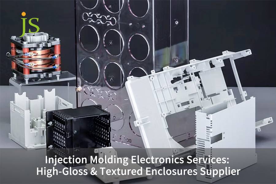
Injection molding electronics is one of the main techniques running those big production lines making the electronic housings we use every day.
Besides being able to produce parts that are precisely shaped and have an appealing look, it is also capable of making the part robust. The dimensional tolerance of electronic housings needs to be controlled within 0.01mm.
Refreshing and cooling technology (RHCM) is the secret weapon for getting rid of weld lines and producing a shiny mirror surface.
The look of consumer electronics products is, in fact, the direct factor determining the brand value, even very small shrinkage marks and weld lines are capable of causing defects in the products.
When the designs of very thin walls are changed for aesthetic reasons, normal injection molding methods are simply not good enough anymore. Injection molding electronics is the main answer to this tricky problem.
Overview of core answers
|
Core Elements
|
Brief Solution Description
|
|
High-gloss Surface
|
Rapid Heat Cycle Molding (RHCM) + NAK80/S136 Mold Steel.
|
|
Textured Finish
|
SPI Standard Matching (Grade A/B/C) + Scratch-resistant Treatment.
|
|
Defect Prevention
|
Hot Runner Balance + Precision Ejection System + Clamping Accuracy Control.
|
|
Advanced Processes
|
Two-shot Molding (2K Molding) and Insert Molding.
|
|
Supplier Selection
|
DFM Analysis Capability + Full-process Quality Control (IQC-OQC).
|
Key Takeaways
- The size variation of electronic housings should be kept within 0.01mm to ensure their proper assembly and shielding efficiency.
- RHCM is a rapid cooling and heating method that can effectively get rid of the welding lines and give a mirror finish.
- Selecting a supplier having SPI surface treatment capability could lead to fewer expenses for subsequent coating.
- JS Precision can provide a complete range of services starting from DFM mold design to mass production through vertical integration.
JS Precision's Experience In Electronics Injection Molding: Why Is It Trustworthy?
Going with JS Precision means you can be totally stress-free about the professionalism and reliability of their mold making service. We have 15 years of experience in this sector to back up our strength through real project results and industry certificates.
JS Precision is far from just fulfilling the requirements of ISO 13485:2016 for medical device injection molding.
In addition to that, we have done tailored works for more than 300 electronics companies in various fields that include smartphones, smart homes, and portable medical devices. We really know how to deal with the major pain points in electronic casing injection molding and protect your projects.
For instance, as a high end smartphone brand, you might have had lots of difficulties with the mid-frame project: the 0.6mm wall thickness, SPI A-1 mirror finish, and an industrial production yield of over 98%.
Working with different suppliers at first didn't solve the problems because weld lines remained, and the deviation dimension was more than 0.02mm. This not only pushed back the launch cycle but also raised the additional costs.
Here, JS Precision will be managing your entire project, through Moldflow analysis the gate location will be optimized, S136 mold steel and RHCM process will be adopted, you'll be able to control dimensional tolerances to 0.008mm, weld line depth will be reduced to below 0.01mm, stabilize mass production yield is at 99.2%, and production cost for each single batch is reduced by $2,000.
So in short, you can rid yourself of the cooperation difficulties and get long-term stable mass production support.
For you, JS Precision's value proposition is mainly its "profit-oriented" approach:
We will help you reduce the design risks starting from the DFM analysis stage and avoid the losses of reworks after mold making, thus saving time and costs; with end-to-end quality control, consistency of every product batch is guaranteed, and with a stable CPK of 1.33.
By exploiting its vertically integrated service capabilities, JS Precision can also aid you in shortening your mold development cycle to 4 weeks, 30% faster than the industry average, thus enabling your products to be launched faster and grab market opportunities.
If you are struggling with issues related to precision, yield, or cost in electronic casing injection molding, feel free to contact us for a free DFM analysis report. Let us use our real-world experience to help you mitigate risks and optimize your solutions.
Why Is Injection Molding Electronics The Industry Standard For Premium Enclosures?
Injection molding electronics not only can meet UL94 V-0 flame retardant requirements, but it is also capable of producing very thin walls ranging from 0.5-1.5 mm thickness and ensuring highest level of dimensional consistencies of CPK1.33 during mass production.
Therefore, it is quite likely that this technology can become a new industrial standard for the production of high-end electronic housings as it leverages thin-wall injection molding to achieve functional integration.
Thin wall injection molding could easily create 0. 5 mm minimum wall thickness for electronic housings
Thin wall injection molding means the wall thickness is less than 1. 0mm and the L/T ratio is more than 1. 5, which will eventually result in lightweighting of product as well as cost savings. The table below shows the main parameters and benefits:
|
Item
|
Specific Parameters
|
Typical Applications
|
Core Requirements
|
Customer Benefits
|
|
Wall Thickness Standard
|
Minimum 0.5mm, conventional 0.6-0.8mm.
|
Smartphone middle frame, watch case.
|
L/T ratio > 150
|
Product weight reduction by 30%-50%.
|
|
Material Requirements
|
PC/ABS melt flow index MI ≥ 18g/10min.
|
All types of electronic enclosures.
|
Flame retardant grade UL94 V-0.
|
Material cost reduced by approximately 20%.
|
|
Equipment Requirements
|
Injection speed ≥ 300mm/s, injection pressure ≥ 200MPa.
|
Mass production products
|
Equipment precision ±0.01mm
|
Production efficiency increased by 25%.
|
|
Dimensional Tolerance
|
±0.01-±0.03mm
|
Precision electronic components
|
CPK ≥ 1.33
|
Assembly qualification rate increased to over 99%.
|
Functional integration reduces secondary assembly: Snap-fit and PCB positioning post are integrated
By direct molding method, we mold the buckles and positioning pins inside the plastic parts, so no ultrasonic welding is required, and the cost per unit can be reduced by 15-25%.
The tolerance of the buckle fit is 0. 05mm, and that of the center distance of the positioning pins is 0. 03mm. Observing the designing of 1°-2° draft angle and R0. 2-0. 5mm root fillet is very important.
Maintaining dimensional stability with a CPK of 1.33 in mass production
The quality level corresponding to a CPK of 1.33 is 99.993%. By implementing a closed-loop control of the mold temperature within ±1°C and carrying out sampling/testing every 4 hours, we manage to limit shrinkage rate to 0.05% and repeatability of injection molding parameters deviation 2%, so that we can say with confidence that mass production is very consistent.
Simply speaking, it means that from every 100,000 electronic casings produced, at most 6 could be of poor quality, and this will result in lowering of rework and after-sales costs significantly.
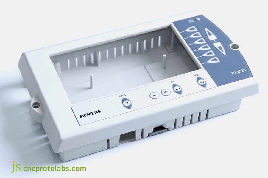
Figure1 : A white and blue injection-molded Siemens control panel component with an "INFO" screen and control buttons.
How To Optimize The Injection Molding Tool For High-Gloss Surfaces?
The glossy appearance of first-class electronic housings is largely determined by the injection molding tool's design which has been optimized.
Mold steel of NAK80 or S136 grade, interfaced with RHCM rapid cooling and heating, multi stage venting channels, and injection mold steel standard ASTM D3675-18 are of the utmost requirement.
Comparison of Polishing Performance between NAK80 and S136 Die Steels
The choice of mold steel directly determines the high-gloss effect and lifespan. The core parameters are compared below:
|
Mold Steel Type
|
Hardness
|
Polishing Grade
|
Surface Roughness Ra
|
Mold Life
|
Application Scenarios
|
|
NAK80
|
HRC 40-45 (pre-hardened)
|
SPI A-2
|
0.025μm
|
< 200,000 molds
|
Semi-gloss, small to medium batch production.
|
|
S136
|
HRC 50-52 (quenched)
|
SPI A-1
|
0.012μm
|
> 500,000 molds
|
High-gloss, mass production.
|
Meanwhile, NAK80 can serve as a more economical alternative for medium- to small-volume semi-gloss purposes.
Basically, S136 is a very tough "luxury tool" capable of making high-gloss surfaces for a long time without breaking down, while NAK80 is an economically "feasible" tool for small-to-medium production. The right choice of a model can give the best blend of both performance and cost.
RHCM (Rapid Heating and Cooling) Process Parameters: Mold Temperature 120-150℃
The RHCM technology helps to minimize the weld lines on the PC from 0.1mm to less than 0.01mm by bringing PC to a temperature of 120-140℃, before filling, and then cooling it to below 60℃ quickly after the pressure holding.
It needs a high temperature mold temperature controller and the production cycle is lengthened by 5-10 seconds. It is the right choice for PC, PMMA and ABS materials.
Exhaust channel depth 0.01-0.03mm to prevent scorching
Scorching happens when compressed air gets so hot (above 250℃) that it chars the plastic. The exhaust path must be positioned in the weld seam and towards the end of the fill.
The PC depth should be 0.01-0.02mm, while for ABS/PP it should be 0.03 mm. Going over 0.05mm will lead to flash. Insufficient exhaustly might make the local temperature reach more than 300℃.
Unsure which mold steel to choose for your high-gloss products? Contact our engineers for free injection mold components selection advice and avoid common mold optimization pitfalls.
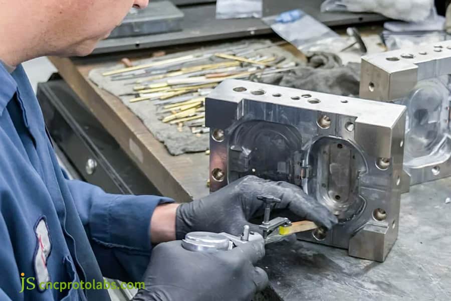
Figure 2: A technician uses a digital caliper to precisely measure a metal injection mold component on a workbench.
Which Injection Molding Surface Finish Best Enhances Your Device's Aesthetics?
The injection molding surface finish determines the look and feel of electronic products.
A high-gloss mirror finish (SPI A-1) is appropriate for high-end smart home panels (which will need a hard coating of 2H), whereas a matte texture (MT-11010) is less prone to showing scratches and is therefore suitable for industrial-grade handheld devices.
SPI A-1 high-gloss mirror finish requires the mold surface finish to be no more than Ra 0.012μm
In order to achieve SPI A-1, polishing has to be carried out with diamond paste gradually (6μm→3μm→1μm).
The mold steel must be completely sealed and show hardness HRC50, also, there should be no scratches visible at 30℃m with a 500 lux light. The time to polish is 3-5 times longer than for A-3, and the cost is 40-60% higher.
MT-11010 matte texture depth range: 20-50μm
MT-11010 exhibits a texture depth of 20-30μm, and MT-11030 is 40-50μm deep. Through chemical etching or EDM treatment, shrinkage marks and flow marks can be hidden. The deeper the texture, the higher the demolding resistance, hence, the demolding angle must be between 3°-5°.
High-gloss surface hardening coating: PVD or UV cured hardness ≥2H
High-gloss surfaces are quite vulnerable to scratches and thus need a durable coating. A typical PVD coating is 1-3μm thick and has a hardness level of 3H-5H.
A UV hard coating is 5-10μm thick and has a hardness of 2H-3H, which is ideal for PC/PMMA. The adhesion should be at least 4B. An uncoated PC has a hardness level of HB, while a coated one can reach 2-3H.
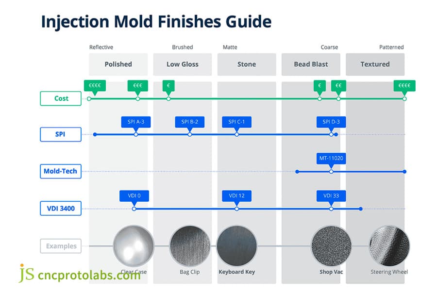
Figure 3: A comprehensive chart comparing different injection mold surface finishes, from polished to textured, with associated costs, SPI/VDI standards, and real-world application examples.
What Are The Differences Between SPI Surface Finish Standards For Electronics?
Electronic injection molding surface treatment directly relies on the SPI surface finish as well. Various grades will be associated with different effects and pricing:
SPI A-1 (Ra≤0.012μm) is the mirror finish grade, B-1 (Ra 0.05μm) is the semi-gloss finish grade, and C-1 (Ra 0.10μm) is the grade for rough functional surfaces. SPI A is 40-60% more expensive than SPI C.
SPI A-1 to A-3: Mirrors Standards for Electronic Products with High-End
- A-1: Ra≤0.012μm, polished with diamond paste, perfect for smart phone back covers and smartwatches aftermarket and with the highest cost.
- A-2: Ra 0.025μm, polished with fine sandpaper and diamond paste, suitable for PC transparent panels.
- A-3: Ra 0.05μm, polished with fine oilstone and diamond paste, best for internal mirror finish parts.
Grade A requires a magnifying glass 10x inspection to be threadless and also to make sure that the scope is free of whiskers and defects.
SPI B-1 to B-3: Semi-gloss finish and a good balance in the cost
- B-1: polished with 600-grit sandpaper, Ra 0.05μm, the same surface as Smart Home Panel, but Cost 30-40% less than Grade A.
- B-2: polished with 400-grit sandpaper, Ra 0.10μm, the surface of the Body of Remote control.
- B-3: polished with 320-grit sandpaper, Ra 0.15μm, the surface of the Function Button.
SPI C-1 to C-3: Rough finish on functional areas
Grade C surfaces are used for internal functional parts, have low demolding force, and the mold processing cycle is more than 50% shorter than that of Grade A. Specific parameters are shown in the table below:
|
SPI Grade
|
Processing Method
|
Surface Roughness Ra
|
Application Scenarios
|
Mold Processing Cycle
|
|
C-1
|
320-grit stone grinding
|
0.18μm
|
Battery compartment inner wall.
|
5-7 days
|
|
C-2
|
240-grit stone grinding
|
0.25μm
|
Internal structural parts.
|
3-5 days
|
|
C-3
|
120-grit stone grinding
|
0.35μm
|
Heat sinks, ventilation grilles.
|
1-3 days
|
Download the SPI surface finish standard form to quickly match your product needs. You can also consult our surface treatment solutions for free to achieve a balance between texture and cost.
How Do Critical Injection Mold Components Prevent Surface Defects?
One of the main issues with the injection molding of electronic casing is the formation of surface defects. Designing the injection mold components reasonably is the main factor in the prevention.
For example, the hot runner valve needle sequence control together with a highly precise ejection system and synchronized movement of the guide pillars and bushings are the major factors determining the surface quality of the product.
Hot runner valve needle sequence control helps to lower flow marks
A hot runner system includes a manifold, several hot nozzles, and valve pins. To reduce flow marks and lower the injection pressure by 10-15%, one can open the valve pins in a sequence (the delay is from 0.1-0.5 seconds, and closing them when the mold is 95% filled).
The gap between the valve pin and the gate should be 0.005mm, and the sealing ring is normally replaced after every 100,000 molding cycles.
Moving from ejector pins to top blocks and push plates totally removes ejector pin marks
Usually, ejector pin marks result from the very high unit pressure of ejector pins. Now, we change them to ejector blocks (area≥20mm²) or push plates.
The chamfer of the ejector block is R0.2-0.5mm, the push plate stroke is demolding distance + 10mm, and the roughness of the ejector block is the same as the cavity (Ra≤0.025μm, data anchor point).
Guide post and guide sleeve clearance ≤ 0.02mm to prevent burrs
Burrs may be caused by a parting surface gap > 0.02 mm. For the guide pillars and guide sleeves, we use MISUMI ultra-precision grade. The fit clearance is 0.01-0.02 mm, and the perpendicularity is 0.01 mm/100 mm. Besides, wear is checked per 100,000 mold cycles.
How To Select Advanced Injection Molding Services For Multi-Material Enclosures?
Multi-material electronic housings require a higher level of injection molding services while also demanding value-added services such as two color injection molding, insert injection molding, and EMI shielding coating, which can satisfy even more complex requirements.
The interfacial strength between two-color injection molded rigid PC and flexible TPE is 4MPa.
Two-color injection molding requires a dual stage rotary injection machine (positioning accuracy 0.02mm, data anchor points).
The most frequently used combinations are PC/ABS+TPE and ABS+TPU, with the bond strength being 4MPa (ISO 36 standard). Also, dovetail groove interlocking can make the strength increase up to 6MPa.
Force needed to pull from injection-molded copper nut 50N
Insert injection molding process will be as follows:
Nut positioning mold closing injection cooling ejection. Pull out forces of M1.6-M3 knurled nuts will be M250N and M380N (USCAR 12 standard, data anchor point). The positioning accuracy is 0.03 mm. Besides, nuts must be preheated to 80-120℃.
EMI shielding coating thickness 10-15μm, shielding effectiveness ≥30dB
EMI shielding coating is one of the most significant and valuable services using copper + silver conductive paint, with a film thickness of 10-15μm, volume resistivity of ≤0.1Ω·cm, shielding effectiveness of 30dB (99.9% attenuation), and an adhesion rating of 4B.
It covers all inner surfaces and is a key to strengthening the service competitiveness of custom molding parts suppliers.
How To Choose a Reliable Custom Molding Parts Supplier For Complex Projects?
The winning of intricate electronic enclosure projects depends on getting dependable custom molding parts supplier. Fundamentally, judging is based on how good DFM (Design for Manufacturing) is, the entire quality management system, and the control of the production cycle.
The DFM report must be supported by Moldflow analysis and include shrinkage compensation
A DFM report shall incorporate 3D, wall thickness, shrinkage marks, weld lines and filling pressure analysis. Moldflow must be aligned with the following criteria:
Filling time < 1.5 seconds, pressure drop < 80% of max injection pressure, PC shrinkage compensation 0.5-0.7%, ABS 0.4-0.6%, no compensation for easy dimensional deviation 0.1mm.
First Article Inspection (FAI) and SPC Process Control
Full-process quality control requirements:
- IQC tests plastic moisture content 0.02%.
- IPQC measures dimensions every 2 hours and records parameters every 4 hours.
- FAI measures 50-100 dimensions.
- SPC performs full inspection on dimensions with CPK <1.33.
- OQC follows AQL Level II standards.
Prototype mold trial (T0) to SOP (Start of Production): Standard cycle 4-6 weeks
The mass production schedule is firstly T0 trial molding followed by T1-T3 modification, then small batch trial production, and finally SOP.
JS Precision standard: 2 weeks to fine-tune the dimensions after T0, 4 weeks to supply a small batch, and 6 weeks to reach SOP, which is 1-2 weeks quicker than the industry average.
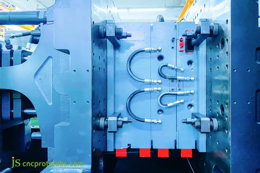
Figure 4: A detailed view of a high-precision injection mold, showcasing the ejector pin assemblies and connected hoses on the parting line, indicating advanced tooling capabilities.
JS Precision Case Study: Smart Home Panels Achieve 90% Weld Line Elimination And Grade A Mirror Finish
Here are some practical, real situations that show JS Precision's technological skills in injection molding electronics. These examples show how we helped customers overcome injection molding issues and achieve efficient mass production.
Difficulties encountered:
The smart panel of a high-end smart home company has three main pain points:
The very thin 0.8mm wall thickness and 180mm length lead to insufficient filling at the far end, the depth of the weld line reaches 0.15mm while SPI A-1 mirror finish is required, and the hardness of the high-gloss surface is less than 1H, resulting in a rework rate of 28%.
Solution:
After taking over the project, we initially employed DFM analysis and Moldflow model flow analysis that helped us locate the root of the problem with high precision and hence propose a precise solution:
- S136 mold steel (HRC 52) is used and vacuum quenched to control the roughness of the mold cavity to Ra 0.01μm so as to have a high-gloss effect.
- The RHCM (Heat-Cool-Cool) method is implemented whereby the mold surface is heated to 140℃ before the filling and thereafter, it is cooled very fast to 60℃ after pressure maintaining which totally gets rid of weld lines.
- The mold venting groove was optimally designed as an annular vent of 0.02mm depth and 8mm width so as to avoid scorching during filling.
- The PVD vacuum coating with a thickness of 2μm that has been added to the surface hardens the surface to 3H, thereby resolving the scratching issue.
Lessons and lessons learned from failure:
The project came across three issues that affected its progress:
- T0 trial mold had to be scrapped as RHCM method was not applied and therefore weld lines were still visible. The key takeaway is that for high-gloss thin-walled components Moldflow simulation should be done in advance.
- The first exhaust channel was too shallow (0.008mm), which led to scorching. A deeper cut of 0.02mm was made and an auxiliary exhaust was also installed.
- An incomplete cleaning step before PVD caused the formation of pitting thereby the addition of a double cleaning step resulted in achieving a adhesion level of grade 4B.
Regarding cost control, after 300,000 mold cycles the initially used NAK80 steel developed scratches. An upgrade of the steel to S136 to carry out the mold repair resulted in a cost increase of $2,000. For high-gloss and large-volume projects, the use of S136 will be the more cost-effective option in the long run.
Final Result:
The weld lines width was minimized to 0.01mm (about 90% of them were eliminated), surface hardness level attained 3H, and rework rate was 4%, cycle time for single-hole was lowered from 45 seconds to 38 seconds, and yield improved from 72% to 96%, T0 to SOP was done in only 5 weeks, 2 weeks earlier than the scheduled time.
Client feedback:
"The thing that pleased us the most was the DFM report from JS Precision that not only identified and clearly showed us the potential risk of shrinkage marks due to the sharp change in wall thickness in the original design but also recommended a change plan.
This way, we didn't have to come to the realization of the issue only after mold making. Overall, the project duration was cut by two weeks against our expectations." -Brand Structural Design Director
Are your products also facing issues such as weld lines, scratches, and dimensional deviations? Submit your product drawings to get a free process solution similar to this case study, quickly implement your project, and reduce costs.
FAQs
Q1: What is the minimum wall thickness that can be achieved for electronic casings?
A wall thickness of 0.5mm can be stably achieved with the latest precision injection molding electronics technology, and in the case of special optimization, it can be reduced to 0.3mm, thereby fulfilling the demands of lightweight and thin portable devices and at the same time ensuring structural strength and dimensional accuracy.
Q2: What are the most common defects on a glossy surface?
The primary defects on glossy surfaces are weld lines and flow marks. If RHCM technology is used along with a well-designed precision mold, then weld lines will be reduced to less than 0.01mm and flow marks can be totally removed.
Q3: What are the main differences between the SPI A-1 and A-2 surfaces?
The main difference lies in the polishing grade and roughness. A-1 is polished with diamond paste (Ra0.012μm, mirror finish), whereas A-2 is polished first with fine sandpaper and then with diamond paste (Ra 0.025μm, a little inferior texture).
Q4: How to avoid the glossy surface getting scratched during demolding?
To prevent scratches on the surface, increase the draft angle to ≥1.5° and replace ejector pins with polished ejector blocks. This not only ensures that the roughness of the ejector blocks is consistent with that of the cavity but also makes the ejection force uniform, so no marks can occur.
Q5: What is the precision in positioning a copper nut in insert injection molding?
With a precision mold, the positioning accuracy of the copper nut can be controlled to 0.03mm. It is secured by a specific positioning pin, and the tight fitting is guaranteed by in-mold detection and preheating of the nut.
Q6: What is the main focus of parameters in DFM analysis?
Mainly, it is to assess the wall thickness uniformity, predict shrinkage marks, identify weld line locations, and analyze the filling pressure curve. This can help in detecting design risks beforehand and avoid mold opening and rework.
Q7: How long does an injection mold typically last?
Electronic molds made of S136 steel are capable of 500,000 to 1,000,000 cycles, whereas those made of NAK80 steel have a lifespan of 200,000 cycles. Based on the scale of mass production, the choice can be made accordingly.
Q8: What is the minimum order quantity (MOQ) for JS Precision?
The prototype stage supports small batches of 100 pieces, while mass production is recommended to be ≥5000 pieces/batch, which can reduce unit production costs.
Summary
To make electronic housings that are visually appealing and highly functional without giving up accuracy, productivity, and low cost, combining injection molding electronics technology with professional supplier services can produce an A-grade high-gloss finish with a 0.5mm thin wall, and at the same time, guarantee dimensional stability with CPK 1.33.
JS Precision, as a reliable custom molding parts supplier, can help you avoid injection molding misconceptions, control costs, and accelerate production pace. Contact us immediately to obtain your free DFM report and cost optimization suggestions, to make your electronic products stand out in terms of appearance and quality.

Disclaimer
The contents of this page are for informational purposes only.JS Precision Services,there are no representations or warranties, express or implied, as to the accuracy, completeness or validity of the information. It should not be inferred that a third-party supplier or manufacturer will provide performance parameters, geometric tolerances, specific design characteristics, material quality and type or workmanship through the JS Precision Network. It's the buyer's responsibility Require parts quotation Identify specific requirements for these sections.Please contact us for more information.
JS Precision Team
JS Precision is an industry-leading company, focus on custom manufacturing solutions. We have over 20 years of experience with over 5,000 customers, and we focus on high precisionCNC machining,Sheet metal manufacturing,3D printing,Injection molding,Metal stamping,and other one-stop manufacturing services.
Our factory is equipped with over 100 state-of-the-art 5-axis machining centers, ISO 9001:2015 certified. We provide fast, efficient and high-quality manufacturing solutions to customers in more than 150 countries around the world. Whether it is small volume production or large-scale customization, we can meet your needs with the fastest delivery within 24 hours. Choose JS Precision this means selection efficiency, quality and professionalism.
To learn more, visit our website:www.cncprotolabs.com
Resource