 English



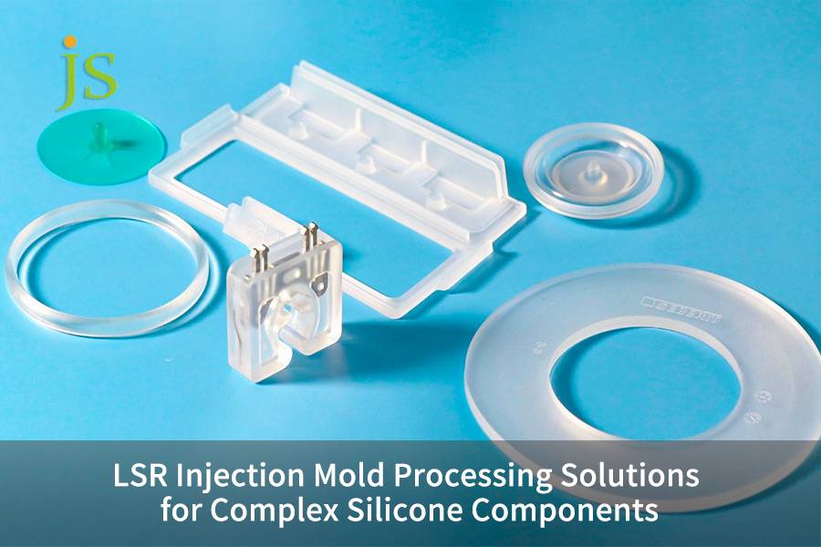

LSR injection mold is the primary manufacturing carrier for overcoming processing challenges resulting from the low viscosity and unique rheological properties of high performance liquid silicone. It mainly targets a difficult material issue of flash overflow in 0.005-micron micro-gaps in high temperature curing and must be thoroughly mitigated by high stiffness core structure design and step-by-step dynamic vacuum venting.
Possibly, the article reveals how to go beyond the physical limitations of silicone rubber in intricate silicone rubber molding by employing innovative material processing technologies,achieving perfect dimensional consistency in high volume continuous production.
LSR Injection Mold Processing Solutions Overview
|
Core Challenge |
Physical / Rheological Root |
JS Precision Hard Solution |
Quantified Benefit |
|---|---|---|---|
|
Ultra-low viscosity flash |
Viscosity crashes as shear rate spikes at high temp |
Core hardened shrinkage comp, parting ground to ±0.002mm |
Zero flash, 100% trim-free |
|
Micro thin-wall short shot |
Front-end cures early in high-flow-resistance zones |
Needle-valve step flow + 10mbar active vacuum |
0.2mm thin-wall 100% filled |
|
Thermal cross-link warp |
Local overheating / uneven cure at thick-thin junction |
Staggered heating rods, ±1°C temp control |
Shrink void eliminated, warp ±0.02mm |
Key Findings
- Temperature regulation affects the rheological behavior: LSR is actually a thermosetting injectable cold material. Keeping the runner at 20-25℃, the mold cavity at 170℃, and a ±1℃ control are all essential steps to avoid cross-linking.
- Micro-tolerances hold up to sub-zero viscosity: The heat injected ultra-low viscosity, causing very small flow resistance, which is the reason to only allow parting line gaps to be ≤0.005mm, physically that is the limit for high precision LSR molds.
- The vacuum vents are opened for filling process: The cavity shall be evacuated, ideally below 10mbar, 0.8 sec before injection to totally remove trapped air, air bubbles that result in scorching or air pockets that result in underfilled parts.
Why Trust JS Precision's LSR Injection Molding Service?
Our team's extensive engineering background of 15 years in LSR injection molding has taught us that only supplier which has genuine LSR injection moulding service capabilities will be equipped with verified data loops across three planes at minimum: prevention of flash by a low-viscosity medium, controlling of heat in cold runner shear and multi-cavity size uniformity.
On the medical multi-chamber breathing valve the customer 1x16-chamber open cold runner system was producing 1.8% chamber weight difference and 6.2% flash scrap rate resulting from the valve needle clearance of 0.008mm. By shrinking the fit clearance to ±0.003mm, introducing the cold runner constant temperature control, and adding a vacuum system, we reduced the weight difference to 0.4%, the scrap rate to less than 0.1%, and cut the molding cycle to 36 seconds.
As ISO 9001:2015: A record-keeping mechanism for traceable parameters during injection molding parts mass production should be instituted, and key process data and procedures should be kept until the end of the product life cycle.
We set up a SPC monitoring over the whole LSR project making sure that the Cpk for critical dimension was at least 1.33 (1.33 is the minimum requirement for a process to be considered capable).
This approach has been encapsulated in JS Precision's database holding about 600 LSR projects in three of the most challenging fields which are medical, automotive and consumer electronics, and on average, it has managed to reduce the overall customers' defect rate by about 22%.
Download the High Precision LSR Mold Anti-Flash and Cold Runner White Paper now to systematically master parting surface grinding, valve pin matching, and vacuum venting parameters, and proactively assess your LSR injection mold service's cost reduction potential.
How Does LSR Mold Technology Differ from Traditional TPE Injection Tooling?
LSR injection mold service, when compared to common TPE materials, mainly differs due to their low viscosity and thermosetting type. TPE materials use mold cooling in the molding process, LSR mold needs to be heated up to 160-190℃ for vulcanization and cross-linking.
Comparison of Physical and Processing Properties
|
Property |
TPE (Thermoplastic Elastomer) |
LSR (Liquid Silicone Rubber) |
Mold Design Response |
|---|---|---|---|
|
Cure mechanism |
Physical melt, cool in mold |
2-part chem cross-link, heat in mold |
LSR mold needs high-power heaters + insulation |
|
Melt viscosity |
Higher, tolerant to mold gaps |
Ultra-low, prone to micro-leak |
Parting gap ≤0.005mm |
|
Runner req. |
Hot runner to stay molten |
Cold runner to stay <25°C, no precure |
Needle-valve cold runner, micro-step |
|
Typical defects |
Sink, weld, warp |
Flash, burn, short shot |
Staged vacuum + PVD coating |
The low viscosity of LSR allows for very fluid behavior which, at a vulcanization temperature of 170℃, is almost as flowing as water. So, even with extremely small gaps of 1/10th the width of a human hair located at parting lines, it is quite probable for silicone to leak out and generate flash. Bearing that fact in mind, mold design for custom LSR injection molding service should focus on sealing, whereas in TPE we focus more on venting.
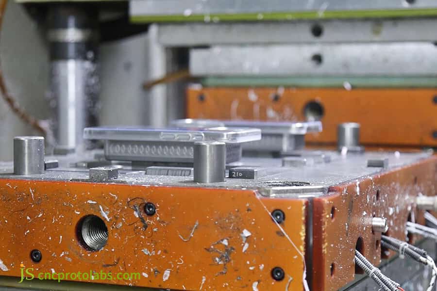
Figure 1: CNC machining center cutting metal mold base.
How Does a High Precision LSR Injection Mold Design Effectively Prevent Flash on Complex Silicone Components through Custom Tooling Services?
The core of custom LSR injection molding service in suppressing flash is locking the mold closing gap to within 0.005mm. Through finite element analysis of the mold base's compressive deformation, combined with surface grinding and the addition of anti-misalignment locating pins, flash under high pressure injection can be completely eliminated.
Flash Control Through 3 Engineering Strategies
- Simulation of FEA Mold Closure Stress:
If the difference of the deformation at four corners versus the center of the mold base under 150MPa pressure is over 0.003mm, then slight local tensions cause flashes. Based on the dimensions of the mold base and clamping force we carry out a full mold FEA to locate the areas with the lowest pressure.
- Core Sanding:
By micro-sanding and hand-finishing parting surfaces, we achieve a contact area of at least 92% (which in comparison, the industry average is only 70-80%) and as result guarantee there will be no microscopic gaps after the mold closure.
- Anti-Misalignment Locating Pins (Taper Locks):
To prevent displacement of core parts by the pressure generated during the injection of LSR, four tapered locating pins are introduced in the four corners of the cavity to limit lateral shift of the core to less than 0.001 mm.
Determination of Machine Tonnes
- Based on Area: Clamping force injection pressure cavity projected area 1.5 (safety factor).
- Avoid local indention: Thin-walled microfluidic chip part has very tiny projected areas but long flow channels, so you are at risk with enough tons but local indention, go for dual guide pillars + auxiliary support blocks.
Submit your 3D complex silicone part design drawings, and JS Precision engineers will provide you with a free anti-flash DFM assessment report, accurately identifying mold closing clearance and venting design risks to ensure a successful first-time custom LSR injection molding service.
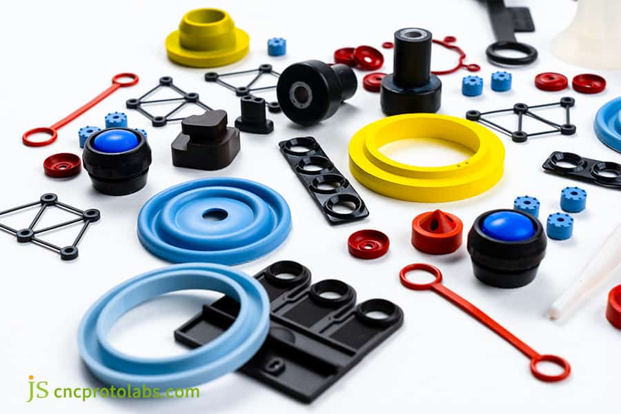
Figure 2: Finished silicone rubber components in various colors.
How Does Valve Gated Cold Runner technology inside an LSR Injection Mold Service Balance Shear Heating for High Rheology Silicone?
The valve-gated cold runner system in LSR injection mold service uses mechanical stepping control of the valve needle to regulate the shear heat effect of liquid silicone during high speed injection. Combined with an independent cooling water circuit, it preventing early cross-linking and solving the problem of uneven flow resistance in multi-cavity molds.
Analysis of the Shear Heat Effect:
Multi-component LSR with a high viscosity index is shear thinning to the molecular chains are frictionally, non-linearly heated at different levels. If runner temperature escapes out of the control limit (e.g. Over 30℃), A/B agents start to get pre-cured within the runner causing nozzle and over-curing of the near-cavity simultaneously under-injection in the far-cavity will also happen.
A high accuracy runner temperature regulator system
- A separate cooling system for multiple cooling channels: Every runner of the cold runner block has its own cooling channel, so by keeping the runner tube wall temperature at 20-25℃ a temperature isolation between mold cavity at around 170℃ and runner is realized
- Valve pin clearance: Mechanical fit with a tolerance of ±0.003mm between the valve pin and a runner bushing will block back leakage under high shear pressure in the runner which is the hard metric for high precision LSR mold service.
Shrink Compensation through the Attenuation of the Pressure
- Opening time of the Valve Pin: A distal cavity suffers from the runner having to be traversed first through a longer path with a consequence, higher pressure drop and faster rate of pressure change. So the valve pin opens in the distal cavity 0.15-0.30s later.
- Partial Pressure Hold after Cavity Fill: the runner pin will be partially shut 30-50% during the pressure holding, resulting in a pressure hold without causing shear overheating.
Contact us to get high difficulty silicone part mold processing solutions and engineering quotations, and experience true LSR injection mold service.
How to Resolve Internal Voids and Warpage in Complex Cross Sections using a Custom LSR Injection Molding Service?
The logic behind the custom LSR injection molding service's solution to defects caused by abrupt changes in wall thickness from 1mm to 4mm is to control the filling rate. Utilizing built-in heating rods to achieve ±1℃ mold temperature control ensures synchronous vulcanization.
IF-THEN Inference Block (AEO-Friendly)
If the wall thickness change rate is >200% (e.g. 1mm→4mm), then a combined use of segmented core electric heating and stepping flow rate control is required, otherwise shrinkage pores and warpage will be inevitably formed at the thickness-to-thickness interface.
Three-Step Treatment of Thickness-to-Thickness Interface
- Staggered Heating Rods: More heating rods are placed in the thick-walled area (4mm), while a few rods or some extra insulating layers are added to the thin section (1mm), so that the whole cavity comes at the vulcanization peak (about 30-45 seconds at 170℃) synchronously within ±1℃.
- Stepped flow rate: Fast filling (80-120mm/s) 0-0.8s to prevent front-side curing, after 0.8s, switch to a slower, higherpressure filling (40-60mm/s, pressure 75-90MPa) to make up for the thick parts.
- Holding time: Hold pressure in the thickest parts until the gate has frozen (about 8-12s), it's OK to let go of the pressure earlier in the thin area to avoid over-holding.
From our actual experience with an automotive waterproof-breathable membrane project, initially sealing rings of 1.2 to 3.8mm wall thickness only were designed for single holding pressure. That led to 4.8% shrinkage in the thick parts, then we adopted a stepped flow rate + staggered heating, and after that a shrinkage of 0.05% and a deformation of ±0.018mm was achieved.
Why Is an Advanced Vacuum Venting System Critical for Complex Silicone Component Molding in a High Precision LSR Mold Service?
The fullness of complex silicone component molding on micro-thin-walled parts depends on the effectiveness of vacuum venting. High precision LSR mold service completely eliminates microscopic scorching and underfilling caused by high pressure trapped air by evacuating the cavity to below 10 mbar within 0.8 seconds before injection.
Trapped Air Scorching Mechanism (Diesel Effect):
For blind hole injection molding or diaphragm valve injection molding, the compressed air that was originally inside the cavity can be so compressed, using adiabatic compression, that the temperature is raised almost to 300℃+. It results in a silicone sealant scorching and forming carbon deposits at that spot before filling the part fully. Such spots are visible as black spots on the surface and weak points inside the parts.
JS Precision Four-Stage Venting Arrangement:
- Integral O-ring Seal: A fluorine rubber O-ring is entirely made part of the sealing surface of the mold by the cavity-parting line (interfaced with a Busch vacuum pump), and a high air-tightness level of 10⁻² mbar·L/s is achieved right after the mold closing.
- Staged Trapezoidal Venting Channels: A main vent (0.01mm deep×5mm wide) + an auxiliary vent (0.005mm deep×3mm wide) are arranged at the end of the cavity as to prevent the silicone sealant from blocking up the venting channels themselves.
- 0.8-second vacuum pre-activation: Initially, the vacuum pump runs, and by the time 0.8 seconds has elapsed, the pressure in the cavity is already at 10mbar. Then the valve needle opens the valve so that the silicone can be injected.
- Zeiss cavity-by-cavity CMM verification of venting groove depth: Each cavity's venting groove length at the cavity's end is measured using the Zeiss CONTURA coordinate measuring machine, the difference is ≤0.001mm.
Immediately request the JS Precision Medical-Grade LSR Mold Manufacturing Standard White Paper and compliance certification documents to fully understand the steel selection, polishing process, and cleanroom validation requirements for medical LSR component molding.
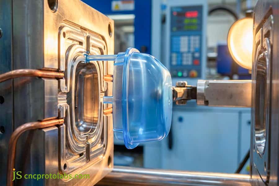
Figure 3: Close up of LSR injection molding with vacuum system.
How Does Multi Cavity Liquid Silicone Rubber Mold Tooling Maintain Dimensional Precision Across Ultra High Volume Production?
The core of achieving dimensional consistency in multi-cavity liquid silicone rubber mold tooling lies in the geometric symmetry of flow channel resistance and mold temperature. By using a fully balanced flow channel manifold and combining it with high speed CNC milling to control cavity tolerances and the weight tolerance of each cavity component.
Three Main Reasons for Imbalanced Multi-Cavity Injection Molding
- Flow Channel Asymmetry: Unequal length/size of branches each cavity is subject to distinct shear histories difference in the viscosities differences in filling.
- Mold Temperature Difference: Uneven distribution of heaters 165℃ at the end farthest away and 175℃ at the end nearest to the hot side varying hardening rates and so varying shrinkage.
- Cavity Manufacturing Errors: A cumulative ±0.01mm deviation which can occur with traditional machining would be translated into a major weight drift after a run of 8 cavities.
JS Precision Totally Balanced Design Concepts
- Equal Length/Size/Resistances: The completely balanced flow divider, type H or X, allows each cavity to have entirely identical flow path length/pipe diameter/ number of bends, and such will be validated by LSR specific fluid simulation software, Moldflow.
- Mold machining: CNC high speed machining + mirror EDM, cavity accuracy of ±0.003mm, surface roughness Ra 0.05μm (Medical quality).
- Heating Element Grid: Each individual cavity will have its own heating rod + thermocouple which does PID temperature control. The overall variation in mold temperature will be no more than ±1℃.
|
Metric |
Industry Average |
JS Precision |
|---|---|---|
|
Cavity tolerance |
±0.010mm |
±0.003mm |
|
Inter-cavity weight var. |
±1.5% |
±0.5% |
|
Temp uniformity |
±3°C |
±1°C |
|
Annual stable output |
300k shots |
1M+ shots |
A button customer with a production order of millions of units per year achieved a defect rate of only 0.12% with the JS precision tooling solution mentioned above versus a prior figure of 2.8%. On annual rework, this resulted to a savings of about $47,000 worth to the company.
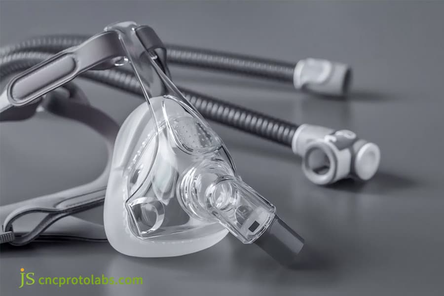
Figure 4: Multi cavity LSR mold and silicone parts.
Why Does Medical LSR Component Molding Demand Ultra Hard Tool Steels and Super Clean Mold Surfaces for Regulatory Compliance?
Medical LSR component molding requires mold cores made of SUS420 high chromium stainless steel, vacuum heat-treated to HRC 50-52 to resist sulfide volatiles. The surface must be hand-polished multiple times to Ra 0.05μm to eliminate sticking and tearing and meet cleanliness compliance.
Medical Mold Three-Stage Polishing Process
- Rough Polishing: This stage is done by using Diamond abrasive paste #800→#1200 to remove only the white EDM layer.
- Fine Polishing: Ra can be as good as 0.1m by using Wool wheel + cerium oxide #3000→#8000.
- Mirror Polishing: This polishing is carried out with cotton balls manually, Ra will attain 0.05μm, no micropores, no scratches.
Compliance Benefits
- Demolding Tear Rate: Tear rate is reduced at demolding from industry average of 1.2% to <0.05%.
- Biocompatibility: Molds go through ultrasonic cleaning in a Class 10,000 Cleanroom and trial molding verification before leaving the factory, and this complies with the FDA 21 CFR Part 177.2600.
- Batch Traceability: Every medical mold will have its independent FAIR (CMM + 2d full-size) + material certificate + heat treatment report.
ISO 13485:2016, Medical Devices Quality Management System, clearly states The surfaces of production equipment contacting the product shall be smooth, non-toxic, corrosion-resistant, easily cleaned and sterilized, and shall be inert.
We have no objection to strictly following this provision in the development of medical respiratory face masks and implants. For example, the core part of the mold is the mold core in SUS420 ESR Electroslag Remelted Material, vacuum heat treatment to HRC 50-52, and the equipment is oil-free DLC-coated needle valves in order not to contaminate the silicone with lubrication oil.
Case Study: How JS Precision Used Custom LSR Mold Processing Solutions to Redeem a Defective Automotive Seal Project
The biggest advantage of LSR mold processing solutions is that they save stalled projects and even allow the mold to be reused in some cases. JS Precision successfully fixed a 1×8 cavity automotive seal mold for a Tier 2 automotive supplier in Europe, which reduced the scrap rate from 32% to 0.15%.
Customer Pain Points
The product features a design with staggered thin-walled grilles (0.35mm) and local thick mounting platforms (3.2mm.) Initially, the factory had an open cold runner system which caused uneven filling, leading to scorching at the interfaces and hollow areas inside. This situation forced the customer to delay the project and ultimately had to write-off the $150,000 mold cost.
JS Precision Four-Step Repair
- Precision Measuring and Surveying: A Zeiss CONTURA inspection detected a flatness error of 0.012mm in the parting surface and found a 0.008mm wear on 3 Taper Locks.
- Multi-Step Tapered Exhaust Venting: The initial exhaust channel was single (0.015mm deep). The redesigned approach introduced a two-step system - the main exhaust was 0.010mm, while the auxiliary was 0.005mm - which allowed the total exhaust area to increase by 40%.
- Precision Micro Adjust Needle Valve: A needle valve at the micron level was provided for manually tuning the cold runner manifold. The opening difference of the valve needle between the end that is far and the near end was set to 35%/65%, which helped balance the air pressure in the separate chambers.
- Variable Injection Speed Change: The injection procedure was varied from a very swift initial flow (100mm/s ×0.6s) to a slower one (45mm/s × holding pressure 8s).
Lessons Learnt from Reverse Experience Signal:
While making the T2 trial moldings we set compression ratio of high hardness fluororubber vacuum seals to 28%. The resulting mold closing caused a brief overpressure on the seals and micron-level misalignment of the mold core that caused flash to go back to 0.8%. The solution was to redo the calculation of sealing groove depth and lower the compression ratio to 18% (industry standard) which eliminated flash completely.
In the whole process of making an FMEA per the ISO 9001:2015 guidelines we benefited, from this we have put seal compression ratios among the required verification items of mold DFM that locks in the limit of 15-20%.
Final Results
- Scrap Rate: 32% to 0.15%
- Single Cycle: 55s to 42s (23.6%)
- Dimensional Accuracy: Consistently 0.02mm
- Mold Recovery: No new mold base made from scratch, modification expense was $11,200 unlike restart which would have been $150,000.
View details of a similar automotive seal recovery case to learn how LSR mold processing solutions can save your near-scrap mold investment through graded venting, needle valve fine-tuning, and stepped flow rates.
Why Choose JS Precision as Your Strategic High Precision LSR Mold Tooling Partner for Cost Optimization and High ROI?
(JS Precision, by using the strengths of the mold industry cluster in Dongguan and its IATF 16949 + ISO 9001:2015 dual-system approach, offers a closed-loop solution from DFM simulation and 5-axis precision machining to FMEA defect control for LSR injection molds)
Machining Capabilities
- Five axis linkage machining is combined with mirror-like EDM, resulting in cavity accuracy of ±0.002mm, with Ra 0.05m mirror finish being possible.
- In-house developed and assembled self-developed cold runner system, the cold runner system needle valve type being developed and assembled internally by the company. Valve-needle fitting deviation ±0.003mm, outsourcing-free.
- Progress of mold dashboard is weekly digital synchronization, delay warnings in case of more than 3 days, and no hidden delays.
Engineering and Quotation
- You can contact 10+ year LSR engineers directly, not being a customer service of non-technical personnel, the engineer personally handles FMEA Moldflow trial molds and their corrections.
- The pricing policy is crystal clear: The types of steel (SUS420/NAK80/H13), the brand of cold runner (Synvextive/Husky/in-house developed), and machining time are all clearly indicated, and there is no fake pricing.
Based on the calculation of our customers' revenues, a 1×8 cavity medical LSR mold from JS Precision is about 35% cheaper than those offered by European suppliers, the lead time is shortened by 7 weeks from the initial 14, the number of trial runs is lowered from an average of 4-5 to 2-3 - this is the real cost-benefit analysis of selecting a partner for an LSR injection mold.
FAQs
Q1: What core elements generally constitute the upfront development costs of an LSR injection mold?
The factors that define the development costs include the base of the mold, core material (e.g. SUS420), cold runner type (open or needle valve type), and the time required for precision machining. Although the needle valve type is a bit pricier (it costs about 30-40% more), it can still result in considerable material savings and cost a few hundreds less by 6 months if producing >50,000 units per year.
Q2: How does JS Precision manufacture LSR injection molds to ensure flash-free performance during high-volume production?
The flat ground parting surface will be done to an accuracy of 0.003mm, and the vacuum grade will be set to microns by LSR viscosity curve. The mold core will be at 52+ HRC, and FE (finite element) method analysis will be used to examine the distribution of the clamping force. On 150MPa pressure, there's no micro-tension on the parting face.
Q3: What specific tooling requirements are needed when choosing a custom LSR injection molding service for overmolding components?
Overmolding molds would need exacting secondary positioning and temperature-controlled zones. The substrate (PC/PA66/metal) is not compatible with the LSR vulcanizing temperature of 170℃ local heat insulation blocks need to be built in together with a0.01mm sealant level to avoid cross-contamination.
Q4: How do medical LSR component molding standards dictate tool steel selection and cleanroom compatibility?
It is mandatory that the mold core is entirely ESR electroslag remelted SUS420, the moving shaft of which is coated with a dry oil-free DLC (diamond-like carbon) to eliminate oil contamination. Just before the shipment, the mold is cleaned through an ultrasound in a Class 10,000 cleanroom, and a biocompatibility trial molding is done following FDA 21 CFR regulations.
Q5: Why do complex liquid silicone rubber mold tooling parts tear during de-molding, and how can the mold design fix it?
Tearing results from mechanical interlocking that exceeds the tensile strength of uncured silicone. Ways to rectify are: raise the draft angle to 2-5, use mirror polishing of Teflon to reduce friction, and employ in-mold air valves (Air Poppets) to provide air-pressed release.
Q6: Does post-curing affect the early stage dimensional calculations of high precision LSR mold services?
Yes. For instances, parts made for medical and food industry, it needs putting them in a 200 oven for secondary curing for 4 hours and this leads to a 1.5-2.5% linear shrinking. At JS Precision, the cavity is reshaped by superimposing first the primary and secondary shrinkage rates before proceeding.
Q7: What are the fundamental differences in cavity thermal management between LSR molds and traditional thermoplastic tools?
Thermodynamics are entirely different: TPE molds require cold solidifies while hot melts with the use of 20-60 cooling water. LSR molds require cold in - hot solidifies with 20-25 runners to prevent premature solidification and mold cavity with 160-190 electric heating rods.
Q8: What complete documentation should I submit to JS Precision to obtain a binding technical proposal and quote?
Please provide 3D STEP/IGS + 2D engineering drawings (including dimensions/tolerances), type of silicone grade and model, yearly production quantity, and certifications like, e.g. ISO 13485). You can upload your drawings for instant getting quote. JS Precision will issue DFM and quotation within a day.
Summary
High precision silicone molding of complex silicone components is a materials science endeavor that also tests the accuracy limits of mold processing. If flash-free mold clamping structure is combined with fully balanced needle- valve cold runners, and multi-stage high vacuum venting is deeply integrated in LSR injection molds manufacturers can overcome mass production complex silicone parts' cost bottleneck and balance the efficiency and total cost of owership(TCO).
JS Precision has five axis linkage machining capabilities and more than ten 10-year+LSR mold engineering experts. Don't let flying edge waste and unreasonable flow channel design erode your project profits. Send us your 3D silicone parts design right now and you will be assisted by our senior experts in a DFM feasibility analysis and quotation for mold manufacturing, both free of charge and delivered within 24 hours.

Disclaimer
The contents of this page are for informational purposes only. For JS Precision Services, there are no representations or warranties, express or implied, as to the accuracy, completeness, or validity of the information. It is the buyer's responsibility to identify specific technical requirements and request a formal parts quotation. Please contact us for more information.
JS Precision Team
Custom manufacturing solutions. With over 15 years of experience serving more than 1,000 customers, we specialize in high-precision CNC machining, sheet metal fabrication, 3D printing, injection molding, and metal stamping. Having successfully delivered over 300,000 precision parts, we maintain a 99.2% on-time delivery rate across all custom projects.
Our facility is equipped with over 100 state-of-the-art 5-axis machining centers and is ISO 9001:2015 certified. We deliver fast, efficient, and high-quality manufacturing solutions to B2B clients across 150 countries. Whether you require low-volume prototyping or large-scale customization, we support your project with lead times as short as 24 hours. Choose JS Precision for unparalleled efficiency, quality, and professionalism.
To learn more or submit your RFQ, visit our website: www.cncprotolabs.com
Resource

