 English



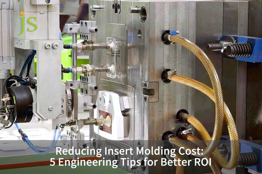

Reduce insert molding cost with our five very effective engineering strategies: insert standardization, wall thickness optimization, retention design, straight-pull molds, and automated loading. Using real project data from JS Precision, these methods might reduce scrap rates drastically from 4.2% all the way to 0.6% and also lower the cost of each part by 30%.
This guide will give you executable parameters, diamond knurl shapes, heating temperatures, volume-related automation limits, so that you can get a higher return on investment while maintaining quality.Keep reading to discover measurable insert molding cost reduction solutions.
Five Strategies to Reduce Insert Molding Cost: A Quick Overview
| Strategy | Key Measures and Quantitative Indicators | Expected Cost Savings |
| Insert Standardization | Use standard knurled inserts (Dodge/PEM standard parts) to reduce non-standard customization. | Insert procurement costs are reduced by 42%, and mold precision requirements are lowered. |
| Wall Thickness & Draft Angle | Standardize wall thickness to 1.2-2.0mm, set a 1-3° draft angle on vertical walls. | Shortened cooling time, reduced shrinkage/warping defects, and decreased unit cost. |
| Retention Design | Diamond knurling + 0.3-0.5mm undercut combination, insert preheating to 80-120°C. | Pull-out force is increased by 3-5 times, interface voids are reduced by 40-60%, and failures are reduced by 60%. |
| Straight-Pull Mold | Design undercut-free parts to avoid slider and ejector mechanisms. | Insert molding tooling cost: Reduced by 20-30%. |
| Automated Loading | Deploy servo turntable + vision inspection system when annual production > 20,000 pieces. | 80% reduction in labor costs per unit, cycle time shortened to 18-22 seconds. |
Key Conclusions
- Introducing standardization and thermal management as part of the solution: heating inserts to a temperature of 80-120℃ before the process can lessen the formation of interfacial voids by 40-60%.
- 20,000 pieces a year is the turning point for automation deciding: under this amount, hand loading is less expensive, over this amount, machine loading is a big win in cost per unit (leading to cost cuts by 18-35%).
- Thickness of the walls cannot be the only factor in insert retention design, the design must also ensure that the difference of the thermal expansion coefficients between metal and plastic is kept below 20 μm/m·℃.
Why Trust JS Precision's Experience In Reducing Engineering Costs Through Insert Molding Service?
With over 15 years of insert injection molding expertise in the automotive and medical sectors, JS Precision ensures that your custom insert molding project benefits from three core competencies: insert standardization, optimized retention force design, and production-driven automated decision-making.
Per our lengthy process testing data set, we discovered that running costs out of control in most insert injection molding projects resulted from the lack of consideration of insert selection, wall thickness coupling, and the timing of automation deployment during the design phase. Sole emphasis on mold structure was responsible for frequent large-scale production defects, very high rework costs, and continuously low yields.
ISO 15527:2019 clearly states that design of insert molds should take into account shrinkage mismatch and thermal stress to prevent cracking.
To meet this requirement, we implemented wall thickness 1.2mm, diamond knurling + 0.4mm undercut grooves, and insert preheating to 90℃ in every project.
For example, in a vehicle ABS sensor project, the original non-standard inserts and uneven wall thickness caused a 4.2% scrap rate. By adjusting the inserts to a standard 1.5mm wall thickness, making the anti-slip structure better, and carrying out automation in loading, the scrap rate dropped to 0.6%, the unit cost went down by 30%, and we achieved an annual saving of $87,000.
The approach we are talking about here is not a one-off instance - it's a systems engineering system that our team has used successively in hundreds of projects, which guarantees that it can be done again and measured.
Want to assess whether your insert design has cost pitfalls? Contact an engineer to obtain the Insert Molding DFM Self-Checklist.
How Do Insert Molding Tooling Cost Factors Impact Total Project Budget?
Insert molding tooling cost is First and foremost influenced by 4 fundamental factors, namely insert size, mold complexity, number of cavities, and loading method. A well-thought-out design could cut down molds costs by 20-30%.
Four main factors determining molding costs
- Insert size and wall thickness requirements: The relation between the outer diameter of an insert and the plastic wall thickness determines the precision level of a mold cavity. Though plastic wall thickness can be as thin as 0.8 mm, a thickness of 1.2 to 2.0 mm is highly recommended. Differences in price for custom insert molding service are mainly due to such details.
- Mold complexity: Side mechanisms and multi-slider designs drastically escalate insert molding tooling cost. A direct-pulling mold can be used to avoid the expensive side-pulling mechanism.
- Number of cavities: By using multi-cavity molds (4 or 8 cavities), the initial mold investment can be spread over larger production volumes. For a project with an annual production volume of>50,000 pieces, the additional mold cost of an 8-cavity conformal cooling mold accounts for approximately 10% of the total mold cost. Still, the cycle time is reduced by 15%, making for a payback period of 29 days.
- Loading method: Manual loading is the best option for low to medium production volumes whereas automated loading is preferable for annual production volumes of >20,000 pieces.
Example of Mold Cost Breakdown
| Factor | Low Complexity | Medium Complexity | High Complexity |
| Insert Type | Standard Brass | Custom Stainless Steel | Non-standard Threaded |
| Number of Cavities | 2 | 4 | 8 |
| Estimated Mold Cost | $12,000 | $28,000 | $55,000 |
| Single Piece Cycle Time | 35 seconds | 28 seconds | 22 seconds |
Reduce insert molding cost from the mold design stage, prefer direct-draw molds and standard inserts wherever possible. The knowledge of the breakdown of mold costs is the first step in streamlining the project budget.
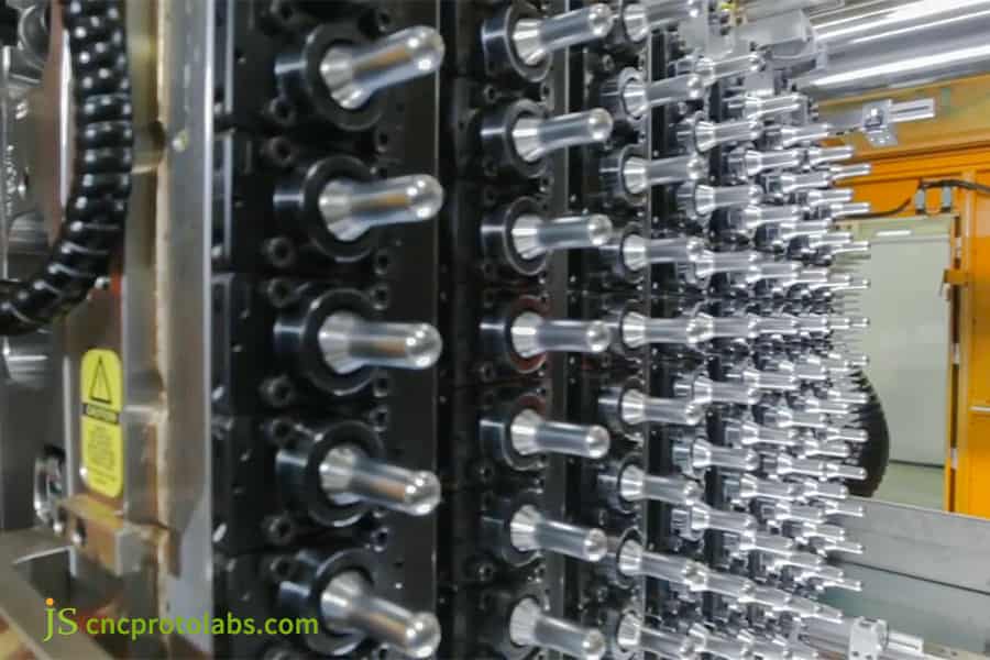
Figure 1: Close-up of injection mold with multiple cylindrical cores and cooling channels.
Why Does Plastic Wall Thickness Around Inserts Determine Insert Molding Engineering Tips Success?
The thickness of the plastic surrounding the metal insert has a direct impact on the defect rate of the injection-molding process and the durability of the mold. If the wall thickness is not enough, it often means cracks, but if it is too thick, the cooling cycle will be longer. The basic rule of insert molding engineering tips is wall thickness is the first parameter to optimize.
Wall Thickness Requirements and Torque Resistance
- Minimum Wall Thickness Requirement: The absolute minimum thickness of the wall around the metal insert is 0.8mm, 1.2-2.0mm is the range preferred for the product to be strong and durable. One way to reduce insert molding cost is standardizing wall thickness.
- Quantitative Relationship Between Wall Thickness and Torque: Suppose we take a metal insert with a diameter of 6mm and the plastic surrounding is PA66. It will result in cracking of a 1.0mm thickness under a 1.5Nm cyclic torque, while a 1.5mm thickness will allow the safe cyclic torque to be about 3.5Nm.
- Thermal Shrinkage Stress: When plastic cools and shrinks it exerts circumferential stress on the insert. The peak stress is halved for every 0.1mm increase in wall thickness.
Wall Thickness Design Rules
- Recommended Range: 1.2-2.0mm for most projects.
- DFM Approval: Any wall thickness of less than 1.2mm will need the approval of a senior engineer before the mold manufacturing stage. Insert molding DFM service brings an assurance of wall thickness compliance right the drawing stage.
- Uniformity: Abrupt transitions should be avoided, use gradual bevels to minimize stress concentration.
Insert molding engineering tips point out that wall thickness is the easiest variable to fix at the design stage. Though, it becomes the costliest rework item once the mold steel has been cut.
Upload your 3D CAD file now—an engineer will return a free DFM report within 48 hours, including wall thickness compliance checks and optimization suggestions.
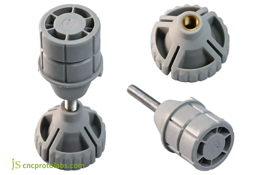
Figure 2: Gray plastic knobs with brass threaded inserts showing wall thickness.
How Does Insert Retention Design Molding Prevent Pull-Out Failure and Reduce Scrap?
Insert retention design molding, like knurling and undercut designs, can increase pull-out force by 3-5 times, which in turn dramatically lowers scrap rates.
Different Knurling Types and Their Performance
- Diamond Knurling: Allows both axial and rotational resistance. A 6mm brass insert pull-out force can hit 3.5-4.5kN in PA66 with diamond knurling. Insert molding engineering tips suggest that diamond knurling should be given a higher priority for retention improvement.
- Straight-line knurling: Only supports resistance against axial tensile force, cheaper but generally weaker in performance than diamond knurling.
- Undercut groove: 0.3-0.5mm deep annular undercut grooves act as a secondary axial locking mechanism separate from the knurling, this is important for environments where vibrations are a factor.
Surface Treatment and Preheating
- Clean Surface: Insert surfaces should be clean and free from grease.
- Preheating: 80-120℃ decrease in metal-plastic temperature difference results in 40-60% reduction of interfacial voids. Besides that, it is possible to reduce insert molding cost by lowering scrap rate through preheating.
Real Project Data (Automotive Sensors)
| Design Version | Knurling Type | Undercut | Pull-out Force (kN) | Scrap Rate | Applicable Scenarios |
| Smooth Insert | None | None | 0.9 | 1.2% Field Failure | Not Recommended |
| Straight Knurling | Straight Knurling 0.3mm Depth | None | 1.8 | 0.6% | Low Load, Static Application |
| Diamond Knurling | Diamond 0.4mm Depth | None | 2.8 | 0.3% | Medium Load, General Industrial |
| Diamond Knurling + Undercut | Diamond 0.4mm Depth | 0.3mm Depth | 3.5 | 0.1% | High Load, Automotive Parts |
| Diamond Knurling + Undercut + Preheating | Diamond 0.4mm Depth | 0.4mm Depth | 4.5 | 0% Field Failure | Highest Load, Safety-Critical Components |
Insert retention design molding is the most economical way to eliminate pull-out failure without increasing wall thickness.
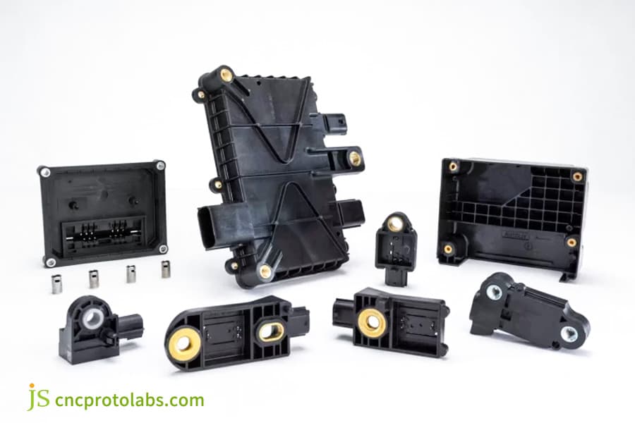
Figure 3: Black plastic electronic components with brass threaded inserts.
How Does Thermal Expansion Mismatch Between Metal and Plastic Affect Insert Molding Quality?
Different thermal expansion coefficients of metal and plastic cause insert molding to develop cracks, warping, and dimensional instability. Insert molding engineering tips recommend making thermal management a part of first stage of design.
CTE Mismatch Quantification Standards
- Threshold: Cooling cracks still occur if the linear expansion coefficients difference between metal and plastic reaches 20μm/m·℃, even with a wall thickness of 3 mm. Thermal management should be the starting point for insert molding ROI optimization.
- Example: The difference between brass (CTE≈20) and PA66 (CTE≈70-100) is around 50-80μm/m·℃, and it is necessary to control the mold temperature and cooling rate strictly.
- Material Strategy: Using glass fiber reinforced materials (like PA66-GF30) lowers the CTE to about 30-40μm/m·℃ and the shrinkage rate to 0.2-0.5%.
Mitigation Methods
- Mold Temperature: Raising the mold temperature increases plastic cooling time and reduces residual stress accumulation.
- Insert Preheating: 80-120℃ can reduce interfacial microvoids up to 40-60%.
- Simulation Verification: JS Precision rely on Moldflow for thermo-structural coupling simulation in each project so that residual stress distribution can be accurately predicted and gate location can be optimized.
The most effective way to reduce insert molding cost is by detecting CTE-related problems through simulation at an early stage, rather than fixing them after the mold steel has been cut.
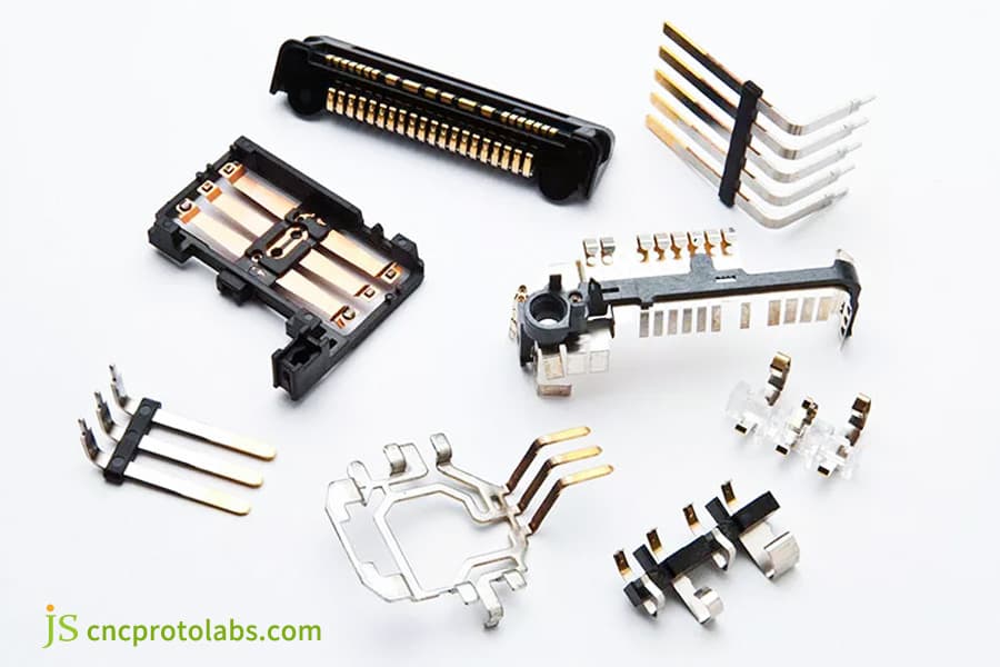
Figure 4: Electronic connectors with metal pins and plastic housings.
At What Production Volume Does Automated Insert Molding Service Deliver Optimal ROI?
Automated insert molding service make automation decisions mainly based on the production volume and labor cost calculations. They calculate that for 20,000 units produced annually, doing the operation manually is still cheaper when compared to automation.
Breakpoint Calculation
Per 45 sec loading time for brass M4 insert with labor rate 30$/hour, the break-even points for manual versus automation are about 18,000-25,000 units/year. In fact, decisions about automation which lead to reduce insert molding cost need to have production volume data very accurate.
Advantages of Automation
- Dramatic labor cost reduction: Automating insert loading can result in a reduction of the role of manual labor to just loading the tray, thereby reducing labor costs per unit by more than 80%.
- Visual Inspection: Checking the position of the insert before injection molding is an effective way to prevent damage to the mold from insert misalignment.
Automation Limitations
- When it comes to automation, the cost increases for very small inserts (less than 3.2mm in diameter) or very deeply embedded inserts, and in turn change the break-even point.
- JS Precision Practice: Our automated insert molding solutions for projects with an annual production capacity of more than 50,000 units come with servo turntables and vision positioning systems, and so the cycle time per piece drops to 18-22 seconds.
The key to inserting molding ROI optimization is to match the level of automation with actual production - neither excessive automation nor insufficient automation.
Unsure where your production volume falls? Download the Automation ROI Calculation Sheet, enter your annual production volume and labor cost rate, and instantly view the payback period for automated installations.
How Does Gate Location Optimization Reduce Scrap Rate and Cycle Time in Insert Molding?
The gate location affects how the molten plastic flows around the insert, which can affect the strength of bond, how much the insert moves and the cooling uniformity. A poor gate location can drop the tensile strength around the insert by 10-40%.
Gate Distance and Weld Line Strength
- Minimum Distance: The gate should be a distance at least 3 times the wall thickness from the insert edge, so that the melt does not come together on the surface of the insert and derive to a weld line.The insert molding DFM service can ensure the gate location is correct at the drawing stage.
ISO 294-3:2020 explicitly mentions: Process conditions of the weld line area and the distance from the gate to weld line should be the controlled parameters of specimen preparation, or tensile strength data cannot compare.
To meet this, we require Moldflow modeling in all new insert injection molds up holds the gate-to-insert edge distance at 3x wall thickness so that the weld line does not fall on the insert surface.
- Strength Loss: The tensile strength in the bonding line area can be reduced by 10-40% compared to the body, which is the main cause of cracking around the insert. Reduce insert molding cost directly reduces scrap rate by optimizing gate position.
- Subgate Strategy: Where the part geometry calls for the gate to be placed close to the insert, utilize a subgate that enters below the insertion centerline. This will allow the melt to hit the insert from the side instead of the front,reducing insert displacement from high-pressure impact.
Mandatory Use of Model Flow Analysis
JS Precision calls for in each new insert injection mold design a Moldflow analysis to check that the distance between the gate and the insert is necessary before moving to the injection mold.
Insert Molding Engineering Tips: Gate location changes at zero additional cost during the CAD phase can drastically cut scrap rate.
How Does JS Precision's Insert Molding DFM Service Reduce Tooling Costs Through Design Review?
Insert molding DFM service helps identify expensive design errors by checking manufacturability through design reviews that take place before mold making, thereby effectively saving insert molding tooling cost.
DFM Review Scope:
- Insert Geometry Standardization: Identify non-standard sizes leading to very high procurement costs.
- Wall Thickness Inspection: Minimum thickness should be ≥1.2mm, any thin-walled areas to be marked.
- Draft Angle Review: Vertical walls should have a draft angle of 1-3° minimum, the rougher the surface texture, the greater the angle required.
- Gate Location Check: Verify the gate position relative to the insert edge.
- Conformal Cooling Evaluation: Compared with traditional drilled cooling, conformal cooling channels can reduce not only the cooling time by 56%, but also the total cycle time by 15%.
DFM Service Process:
- The client sends the STEP files and insert specifications.
- JS Precision will send a thorough DFM report within 48 hours, pointing out all potential hazards and changes with estimates of costs. It all starts with this report that tool costs for insert molding are reduced.
Insert molding DFM service usually spots 3-5 design changes per project, with each change being a hundred to thousand dollars worth of avoided rework.
How Did JS Precision Reduce Automotive Sensor Insert Molding Cost by 30% Through Design Optimization?
Customer Challenges:
A Tier 1 automotive supplier was using custom stainless steel inserts for their ABS sensors. The inserts had external M5 threads but the crying issue was that the wall thickness was not uniform, varying from 0.8-2.5mm. This led to a high scrap rate of 4.2%, and the main causes were the inserts getting displaced and cracking. The starting point of insert molding ROI optimization is to identify these implicit costs.
JS Precision Solutions:
- Inserts Standardization: Replace non-standard inserts with standard brass threaded inserts (Dodge standard inserts), reducing procurement costs by 42%. The standardized selection of custom insert molding service directly brings cost savings.
- Wall Thickness Redesign: Normalizing the wall thickness to a 1.5mm flattened the stress concentration in going through the thickness transition zone.
- Retention Force Upgrade: Applying an addition of diamond knurling and 0.4mm undercut pushed the pull-out force above 4.5kN from just 1.2kN level.
- Automated loading: Installing a servo turntable system cut down the time for manual loading to just 6 seconds from 52 seconds/piece.
Lessons Learned:
Only increasing wall thickness without changing the knurling structure led to an increase in the pull-out force to 1.8kN, which was still lower than the customer requirement of 3.5kN. The eventual solution involved simultaneous changes to the wall thickness, knurling, and the mold temperature control (the mold temperature was raised from 60℃ to 90℃). Getting insert molding DFM service cuts excluding costs through trial and error.
Final Results:
- Scrap Rate: 4.2%→0.6%
- Unit Cost: 30% Reduction
- Annual Production: 120,000 pieces
- Annual Savings: $87,000
By adopting plug-and-use DFM strategies, you can pinpoint and effectively cut down the non-value added activities in insert molding without sacrificing quality or engineering standards.
Your project may also have similar hidden savings opportunities. Upload your 3D CAD files (STEP/IGS), and we will provide a free DFM and cost optimization solution within 48 hours.
Why Choose JS Precision as Your Custom Insert Molding Service Partner for ROI Optimization?
Custom insert molding service involve much more than just making molds. They require complete engineering support, starting from designing the product to mass manufacturing. JS Precision provides data-driven DFM services and automated production lines to help customers achieve insert molding ROI optimization.
Our Engineering Support Services from Start to Finish
- Standardized Insert Selection: Leveraging our extensive project database, we identify the best insert models which are standard, thereby avoiding extra costs and longer lead times due to non-standard customization. The Insert molding DFM service starts from the insert selection phase.
- Mold Flow Analysis and Conformal Cooling Design: By performing a thermal-structural coupled simulation in Moldflow, we have come up with the best gate location and cooling channel arrangement that have helped us reduce the cooling time by 56% and cut the overall cycle time by 15%.
- Automated Production Line Integration: We offer complete automation solutions for projects producing more than 50,000 pieces annually. Using servo turntables and vision positioning systems, we can cut down the cycle time of a single piece to 18-22 seconds.
Quantified Commitment and Service Response
- Transparent Pricing: In the quote of every project, there will be predicted insert pull-out force, estimated cycle time, and a cost-per-production ratio comparison table, so clients can clearly foresee the ROI even before investing in molds.
- 48-Hour Rapid Response: We send a detailed quotation with a DFM report within 48 hours of receiving the drawing. It highlights all the potential risks and the modifications we suggest.
- Wide Material Coverage: The company works with brass, stainless steel, aluminum inserts, and also engineering plastics like PEEK, PA66-GF, and LCP. Maximum part size supported is 480mm×751mm×101mm.
Reduce insert molding cost starts with the right partner - a partner who can identify issues during the design phase, rather than discovering them after the mold steel is cut. The final implementation of insert molding ROI optimization depends on the engineering depth of the partner.
Take Action Now: Upload your 3D drawings and receive a free DFM report and a customized insert molding service quote. Make your next project more profitable.

FAQs
Q1: Which method is more cost-effective, insert molding or thermoforming?
If the annual production volume of your project is below 18,000-25,000 units, thermoforming will usually have lower mold costs and be more economical. But, after production exceeds this level, insert molding per unit cost becomes so low that the overall cost can be dropped by 18-35% by switching to insert molding.
Q2: How to stop insert misalignment and waste during insert molding?
To prevent insert misalignment, engineers must incorporate locating pins into the mold, controlling the clearance between the pin and the mold cavity at 0.01-0.03mm. For very large volume projects, an automated loading + vision inspection system will ensure the proper orientation of every insert before injection molding.
Q3: What is included in JS Precision's Insert Molding DFM service?
These services involve assessing insert geometry standardization, performing wall thickness compliance check (mandatory 1.2mm), providing draft angle tips (1-3°), optimizing gate location, predicting pull-out force and torque, and designing conformal cooling scheme. A complete report will be given back within 48 hours after uploading the drawings.
Q4: What is the minimum order quantity for Custom Insert Molding Service?
JS Precision has formed the product range from 25 prototypes (using aluminum molds for rapid prototyping, lead time 7-10 days) to the mass production of millions of parts. For high production, steel molds or multi-cavity molds shall be chosen as the annual production volume.
Q5: How can I get a quote for insert injection molding?
Kindly provide your 3D part drawings (STEP or IGS format), insert specifications (including material, dimensions, and supplier model), and the estimated annual production volume to JS Precision. We will respond with a cost quote and a detailed DFM analysis within 48 hours. You can upload drawings to obtain a quotation.
Q6: What insert injection molding material combinations are most likely to cause cracks?
Due to the large difference in their coefficients of thermal expansion (the difference is around 50-80μm/m·℃), the combination of PA66 and brass is most likely to cause cracking. However, the difference between PEEK and stainless steel is quite small (around 10-20 μm/m·℃), so the risk is relatively low.
Q7: Do insert preheating have big effect on injection molding quality?
If inserts are heated in advance to the temperature of 80-120℃, the number of tiny pores at the metal-plastic interface can be cut down by 40-60% and the force needed to pull the insert out can be raised by 20-30%. If inserts are not preheated, cold inserts will cool the plastic around them too quickly, that will result in a weak layer.
Q8: What is the usual cycle time of insert injection molding?
The working cycle for very small inserts (less than M4) in a 4-cavity mold can be shortened to as little as 18-22 seconds. More substantial parts and complicated inserts need longer cooling times. The use of conformal cooling molds can reduce the cooling time by 56% and the overall cycle time by 15%.
Summary
The main way for reducing insert molding costs is the focus on three engineering aspects: standardization of wall thickness (1.2-2.0mm),design of insert retention force (diamond knurling + undercut grooves) and production-driven automated decision-making (annual production > 20,000 pieces). The most dangerous effect of thermal expansion mismatch is insert cracking. It should be controlled by methods like mold temperature control, insert preheating, and material matching. Results from JS Precision show that DFM audits reduce scrap rates from 4.2% to 0.6% and unit costs by 30%.
Are you looking for ways to lower the cost of insert injection molding? JS Precision's custom insert molding receives orders for the entire process including DFM audits and automated mass production. Submit your 3D drawings for a free DFM report and a custom insert injection molding quote. We shall respond within 48 hours and provide pull-out force prediction, cycle time estimation, and a production-scale cost comparison table.
Disclaimer
The contents of this page are for informational purposes only. For JS Precision Services, there are no representations or warranties, express or implied, as to the accuracy, completeness, or validity of the information. It is the buyer's responsibility to identify specific technical requirements and request a formal parts quotation. Please contact us for more information.
JS Precision Team
ustom manufacturing solutions. With over 15 years of experience serving more than 1,000 customers, we specialize in high-precision CNC machining, sheet metal fabrication, 3D printing, injection molding, and metal stamping. Having successfully delivered over 300,000 precision parts, we maintain a 99.2% on-time delivery rate across all custom projects.
Our facility is equipped with over 100 state-of-the-art 5-axis machining centers and is ISO 9001:2015 certified. We deliver fast, efficient, and high-quality manufacturing solutions to B2B clients across 150 countries. Whether you require low-volume prototyping or large-scale customization, we support your project with lead times as short as 24 hours. Choose JS Precision for unparalleled efficiency, quality, and professionalism.
To learn more or submit your RFQ, visit our website: www.cncprotolabs.com
Resource

