
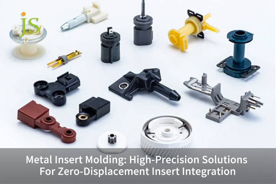
Metal insert molding, especially the precision injection molding, is one of the main manufacturing processes used for producing high end products that require precision and quality such as electronics, automobiles and medical devices.
In precision injection molding, the main concern when metal insert is integrated into the plastic matrix is not how to put it, but how to make sure it does not move.
For miniaturized and highly reliable products, a small movement of 0.05mm is a disaster, which may cause the product to malfunction or assembly failure by 0.1mm
For the complex process of insert molded components metal stamping, do you decide to accept fluctuating rejection rates after mass production or do you control each step of the process and achieve zero displacement from the source?
Core Answer Summary
| Core Challenges | Key Points of Zero Displacement Solutions |
| Root Causes of Insert Displacement | Sudden stress imbalance during the melt filling stage is the primary cause of displacement, not just mold accuracy. |
| Design Level Prevention | By employing DFM displacement risk assessment and mold flow analysis, 80% of displacement issues can be prevented at the design stage. |
| Mold Locking Structure | The combined structure of "mechanical error prevention + floating positioning" is used to obtain accurate positioning and active retraction before and after mold closing. |
| Cumulative Tolerance Control | Automated roll-to-roll machining and visual inspection remove cumulative errors between stamping and injection molding. |
| Mass Production Assurance Mechanism | The real time monitoring and closed loop control of in mold pressure curves provide early warning and intervention for displacement defects. |
Key Takeaways
- Preventable Displacement: It is possible to avoid 80% of displacement problems by performing mold flow analysis and DFM review during the design phase.
- Data Driven Accuracy: Precise adjustability of insert positioning can be achieved by utilizing sophisticated mold design and process control, resulting in an accuracy of 0.01mm.
- Cost Effective Integration: Choosing suppliers with the custom insert injection molding ability can greatly cut the total cost of ownership via functional integration.
Why Trust This Guide? JS Precision's Experience In Metal Insert Molding
Having more than 15 years of dedication to precision manufacturing, we mainly concentrate on the metal insert molding and other insert molding processes.
Throughout these years, we have manufactured more than 300,000 hold insert parts for 1,000+ clients worldwide with a 99.2% on time delivery record while also being holders of ISO 9001:2015 and ISO 13485 certifications which are major verifications of our professionalism.
So, by entrusting your insert molding project to us, you will get high quality and stable insert molding services without sacrificing your project time even if there are some unexpected problems with the project or the quality in.
We have a well developed factory that completely owns CNC machining, injection molding, and line production of stamping/injection molding integrated.
Through the years of metal insert molding, the insert displacement problem has been a major concern and we came up with a solution in the form of a closed loop system which includes DFM analysis, mold design, process control, and mass production monitoring.
We have helped more than 500 premium clients solve their insert displacement problem by, among other things, providing the types of solutions used in the high end industry examples of these being automotive sensors, medical implants, electronic connectors, etc. Our experience covers way more than the industry average in these areas.
We adhere to ISO 13485 medical manufacturing standards, and all processing and quality control parameters are in line with internationally accepted standards to guarantee the accuracy and reliability of each insert molding part.
Our engineering team members, in average, have over 10 years of direct experience in insert molding, and they can answer your technical questions within 15 minutes. We provide free DFM (Design for Manufacturability) analysis, using real data and successful case examples to protect your projects.
We are not just processing service providers, we serve as your technical partners, assisting you in minimizing displacement risks at the design phase, and attaining zero defects in mass production.
Per the SME report, the average industry insert displacement defect rate is 3.2%, but we have aided many automotive parts clients in lowering this figure from 5% to under 0.2%, each customer saving over $100,000 annually.
By selecting us, you will have a one stop metal insert molding solution at your disposal from the prototype stage through to the mass production stage, thereby eliminating displacement problems in precision insert molding.
Contact our engineers now to receive a free metal insert molding white paper, quickly master the core zero displacement process, and proactively mitigate project risks.
What Is The Culprit Behind The Displacement Of The Insert In Metal Insert Molding?
Displacement of the inserts is not a result of mold manufacturing errors, but rather the instantaneous impact and shear forces that the melt flow generates during injection molding, which disrupt the force balance of the insert and cause small displacements on the order of microns.
Mel front impact disrupts the initial positioning of the insert
We use a 10000fps high speed video to observe the melt front sighting the insert, and from it, we estimate the peak impact force at 50-200MPa. Each 10MPa increase in impact force corresponds to a displacement increment of 0.003-0.005mm, which is the main cause of production defects for many customers.
Uneven shear force distribution and filling time difference cause deflection
We trace the melt flow front arrival time difference at both sides of the insert, any difference of more than 0.1 seconds will cause a significant displacement.
We set the limit conditions: symmetrical filling is appropriate for inserts with an aspect ratio > 8, and a low speed, high pressure filling is suitable for thin walled parts with a wall thickness < 1.5mm. ISO 9001:2015 standard control of filling parameters should be done accurately.
How to Eliminate Displacement Hazards from the Design End in Custom Insert Injection Molding?
Design phase is where 80% of displacement problems start.
By performing initial Design Flow Modeling (DFM) displacement risk assessment together with mold flow analysis, the structure of insert can be changed on the drawings to the extent of minimizing displacement risk at the lowest cost.
Three Core Indicators for DFM Displacement Risk Assessment
- Insert L/D Ratio: Ideally, it should be under 10:1.If this ratio is exceeded, the add locating holes and support structures will be inevitable.
- Plastic Wall Thickness Uniformity: Variation in wall thickness should be kept under 0.2mm so as to prevent uneven shrinkage that will cause deflection of insert.
- Relative Relationship between Gate Location and Insert: Gate should not be directly aligned with the insert, the minimum distance >3mm.
Mold Flow Analysis Predicts Displacement Trends and Guides Design Optimization
We perform filling analysis in Moldflow or Moldex3D and can predict displacement trend with 90% accuracy. Afterward, we suggest inserting locating holes, improving chamfers, and changing insert thickness to get rid of displacement risks from the stage of drawing and at the same time, cut mold modification costs by 60-80%.
Cost Comparison Table for Custom Insert Injection Molding Design Optimization
| Design Stage | Displacement Risk Mitigation Cost | Mold Modification Probability | Project Cycle Shortening Percentage | Insert Positioning Accuracy |
| No DFM Analysis | $10,000-$20,000 | 85% | 0% | ±0.05mm |
| Basic DFM Analysis | $3,000-$5,000 | 40% | 20% | ±0.03mm |
| Deep DFM + Mold Flow Analysis | $1,000-$2,000 | 5% | 40% | ±0.01mm |
| Pre-Production Optimization and Verification | $500-$1,000 | 1% | 60% | ±0.008mm |
Get a free custom insert injection molding DFM report. We will combine your design drawings to identify displacement risks in advance during the design phase, reducing project trial and error costs.
How to Achieve Zero Displacement with Mold Lock in Injection Molding with Metal Inserts?
The main element of obtaining zero displacement is to design a mold positioning system. The insert is fixedly locked before mold closing, and during filling, it continually repositions itself to counter clamping forces and melt impact.
Mechanical error prevention + floating positioning composite structure:
First, the insert is locked by the rigid locating pin before mold closing. The diameter tolerance of the locating pin is strictly controlled from -0.005mm to 0mm.
The positioning mechanism, which is spring or cylinder driven, is retracted in the last 2-3mm of the mold closing stroke to allow the plastic to completely surround the insert without any stress due to interference.
Design concepts and guarantee of the lifespan of zero clearance locating pins:
We choose SKD61 or powder high speed steel for the locating pins, treat them by quenching and tempering to HRC58-62, and apply TiAlN or CrN coating to reduce the friction coefficient to less than 0.3.
This will guarantee that the positioning accuracies remain stable within 0.01mm after 1 million mold closing cycles.
Performance Parameter Table of Locating Pins for Injection Molding with Metal Inserts
| Locating Pin Material | Heat Treatment Hardness | Surface Coating | Coefficient of Friction | Maximum Service Life | Long Term Positioning Accuracy |
| SKD61 | HRC58-60 | TiAlN | 0.28 | 1 million molds | ±0.01mm |
| Powder High-Speed Steel | HRC60-62 | CrN | 0.25 | 1.5 million molds | ±0.008mm |
| Stainless Steel | HRC52-55 | TiN | 0.35 | 500,000 molds | ±0.02mm |
| Carbon Steel | HRC45-50 | Uncoated | 0.5 | 200,000 molds | ±0.05mm |
Submit your product drawings, and we will customize an injection molding with metal inserts mold locking structure solution for you, precisely matching your zero displacement requirements.
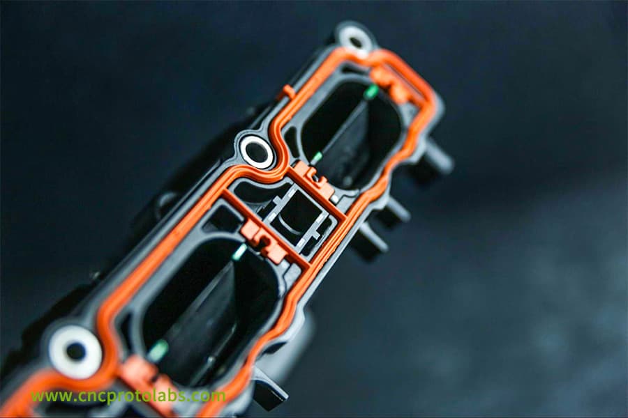
Figure 1: A close-up view of a complex black automotive sensor component with integrated orange metal inserts, showcasing precise overmolding.
How To Solve The Problem Of Tolerance Accumulation Between Stamping Accuracy And Injection Molding Accuracy In Insert Molded Components Metal Stamping?
Breaking the tolerance chain by employing internal mold guide pins to position the stamped strip accurately for the second time is an effective way to ensure that the tolerances of the stamped part do not have any influence on the final product.
Automated roll-to-roll process eliminates manual placement errors
We feed the continuous stamped strip directly into the injection molding machine without any manual intervention. This way, placement errors of 0.02mm are completely avoided.
Secondary precision positioning using internal mold guide pins limits the gap to 0.005-0.01mm, thereby maintaining the high level of mass production accuracy in insert molded components metal stamping.
Visual inspection ensures insert quality:
Online check of the insert quality is done through a 5-megapixel industrial camera, which is capable of inspecting with an accuracy of 0. 005mm. The inspection includes looking for burrs, flatness, and accuracy of the positioning hole.
By this, we are 100% sure that only those inserts which have a CpK > 1. 33 are allowed to be molded in the cavity and the rejection time is <0. 5 seconds.
How To Solve The Displacement Problem Caused By Long Cantilever And Gravity Sag For Large Part Injection Molding?
The biggest challenge for slender inserts is gravity induced sagging. The combination of multi point dynamic support with sequential filling system and mold temperature zone control creates an effective solution against gravity and nonsymmetrical shrinkage.
Multi point dynamic support to compensate for gravity induced sagging
We have installed retractable auxiliary support blocks in the mold which create support points that are spaced at <50mm distances. The blocks achieve simultaneous removal after mold closing together with filling which solves the displacement problem that occurs with long cantilever inserts during large part injection molding.
Sequential filling and mold temperature zone control to prevent uneven shrinkage
Our system uses sequential valve gate technology to control the melt filling sequence which produces a filling time difference of <0.05 seconds between the two insert sides.
Mold temperature zone control maintains a temperature difference between two ends at ±5°C which leads to a shrinkage rate difference of <0.1% that reduces displacement deflection.
How Can Custom Insert Injection Molding Meet Complex Needs Under Extreme Conditions?
For extreme working conditions such as high temperature and high corrosion, we provide PEEK/PPS and special alloy combination solutions to solve conflicts in multi insert layout and reduce total cost of ownership through functional integration.
Material Combination Solutions for High Temperature and High Corrosion Environments
We provide two types of custom insert injection molding material combination solutions which include PEEK and titanium alloy with Inconel (operational temperature 260°C) and PPS and 316L stainless steel (operational temperature 220°C) both of which achieve interfacial shear strength greater than 35MPa.
Spatial Layout Solution for Parallel Insertion
Our single mold can simultaneously embed 8-16 inserts, which the system uses a robotic arm and vision positioning system to embed with an accuracy of ±0.02mm.
The system achieves spatial conflict resolution through its two methods of layered positioning and staggered arrangement, which requires a minimum distance between inserts of 1.5mm.
How Does Functional Integration Reduce Total Cost of Ownership?
Our process combines multiple functional elements into one insert molding system which leads to a 50-70% reduction in required assembly tasks.
After sensor integration the customer experienced an assembly time reduction from 45 seconds to 8 seconds which resulted in 35% cost reduction and better production efficiency.
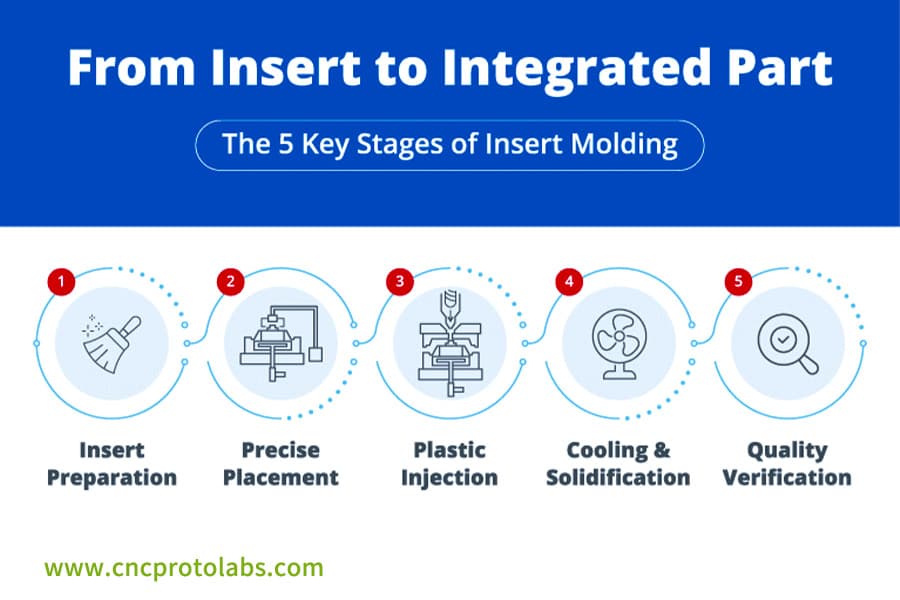
Figure 2: An infographic illustrating the five key stages of insert molding, from insert preparation and precise placement to injection, cooling, and quality verification.
Which Technical Capability Is The True Guarantee Of Zero Displacement When Choosing An Insert Molding Service?
The key to production stability in mass manufacturing is using data driven control. A supplier who can promise zero displacement deliveries should have a real time monitoring system and a closed loop control system for in mold pressure curves, which will allow them to trace production status.
In mold Pressure Curve Monitoring Enables Process Traceability
We use piezoelectric pressure sensors installed inside the mold cavity to measure the pressure curve of each mold at a 10kHz sampling rate.
We record eight feature values to create a "process fingerprint" which gives us 100% data traceability and leads to controllable mass production accuracy of the insert molding service.
Early Warning of Displacement Defects
We make a correlation model between the pressure curve and insert position (R²>0.95).
The system will automatically give an alarm within <0.2 seconds if the pressure curve changes by ±3σ, the system will be able to intervene by the time the alarm goes off to avoid defective production. Displacement defect rate is controlled at the level of <50ppm.
Case Study Of JS Precision: Automotive Sensor Insert Molding: Displacement Defect Rate Ranging From 5% To 0.2%
Challenges Encountered:
An overseas automotive parts customer needed to begin mass production of automotive sensor metal insert molding, requiring four copper terminals to be embedded in a PBT substrate with a terminal spacing of 2.5mm and a maximum allowable displacement of ±0.05mm.
The customer used injection molding parameter adjustments during their first mass production attempt yet the process did not solve their problem which resulted in a 5% displacement defect rate.
The system experienced operational interruptions because the terminal spacing exceeded the appropriate limits which resulted in production costs that exceeded $120,000 every year. This is a common pain point faced by many automotive parts customers.
Solution:
After we received the project assignment, our team created an engineering team that dedicated their efforts to find out all the main causes behind the displacement issue.
We executed three particular optimization actions to solve the problem.
1. Mold Structure Optimization: Adopting a composite structure of "floating positioning+sequential evacuation", the gap between the positioning pins is precisely controlled at 0.005mm, eliminating the offset of the embedded mold from a hardware perspective.
2. Process Control Upgrade: An in mold pressure monitoring system was introduced, and a correlation model between the pressure curve and terminal displacement was established (R²=0.97), enabling real time early warning and intervention for displacement issues.
3. Incoming Material Quality Control: A high precision visual inspection step was added to the stamped terminals, which completely eliminated defective incoming materials that had flatness exceeding 0.03mm. This process prevents tolerance accumulation from the source.
Final Results:
The project reached stable mass production after three weeks of debugging and optimization work. The displacement defect rate decreased from 5% to 0.2% which resulted in 99.8% yield and CpK value increase from 0.85 to 1.45 which met all requirements for high end automotive manufacturing standards.
The customer experienced a 90% reduction in assembly line downtime which resulted in annual cost savings of about $120,000. The metal insert molding end-to-end solution proved effective after continuous production of 500,000 molds which maintained positioning accuracy at ±0.01mm.
Get detailed information on this insert molding for automotive electronics case study now and refer to the experience of implementing similar metal insert molding solutions to quickly solve your insert displacement problems.
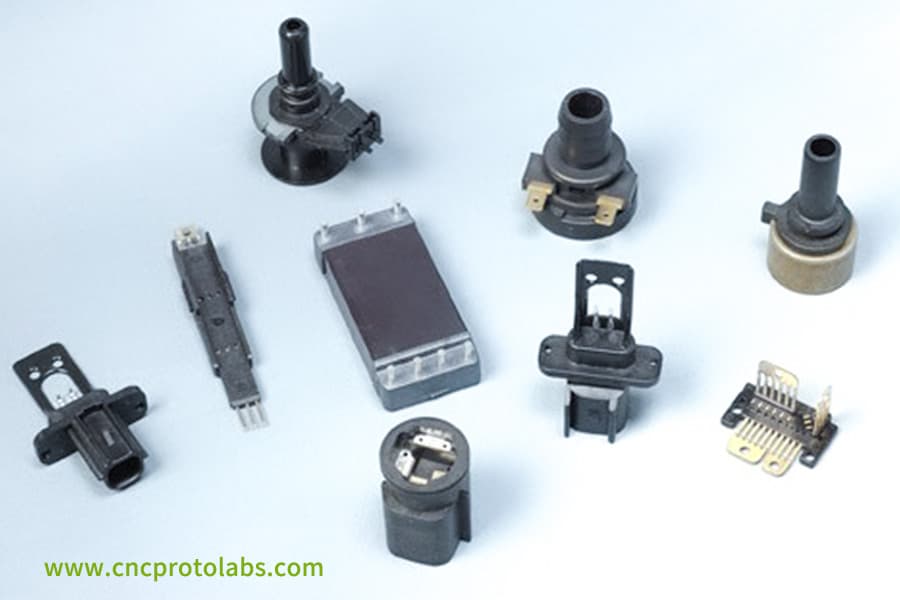
Figure 3: An assortment of various black plastic components with integrated metal inserts, arranged on a light surface, demonstrating diverse applications.
FAQs
Q1:What is the minimum insert size that can be embedded in metal insert molding?
In metal insert molding, we are able to embed micro inserts as small as 0.3mm diameter, with a positioning accuracy of 0.01mm, which is stable and sufficient for manufacturing a wide array of micro precision components.
Q2:What are the material options for inserts?
We offer processing of various metal inserts, including copper, aluminum and stainless steel, along with embedding of non metallic parts like ceramics and PCBs, thereby giving the production teams in different scenarios a wide range of choices.
Q3:How do you ensure the bonding strength between the insert and the plastic?
Surface modifications such as knurling, grooving or chemical treatments, physically strengthen the binding interface of the inserts to the plastic up to 20-50 MPa, which is considerably higher than the strength of conventional physical bonding.
Q4:What is the mold life?
The molds are subjected to heat treatment of HRC58-62 and coated for protection. As per the standard production conditions, a metal insert molding mold can be used for 1-2 million molding cycles.
Q5: What is the duration of a sample production cycle?
Sample lead time for the standard metal insert molding is 10-15 working days, and complex structure leading time is about 3-4 weeks, which can effectively meet the sample verification requirements.
Q6: How to deal with the problem of large inserts sagging due to gravity?
For large inserts sagging problem caused by gravity, multi point dynamic support structure with a support point spacing of <50mm will be used. Supports are placed after mold closing and then taken away gradually during filling, this is the way how we deal with the issue of gravity sagging large inserts.
Q7: What is the dimensional accuracy of the molded inserts?
Our molded inserts conform to injection molding accuracy of 0.05mm, and the insert positioning accuracy is carefully limited to 0.01mm, meanwhile ensuring the requirements of high end precision making.
Q8: How do you guarantee the position accuracy of many inserts embedded in parallel?
Automatic embedding of the composite use a robotic arm with vision positioning. Each mold can be used for embedding 8-16 pieces. Positioning accuracy for the overall is 0.02mm, which can satisfy the accuracy of positioning for multiple inserts embedded in parallel.
Summary
Metal insert molding with zero displacement achievement is never a matter of only optimizing a single process step, but rather a systematic achievement of the entire chain of design, mold making, process engineering, and mass production control.
No more need to worry about defect rates, high costs, and low efficiency caused by insert displacement. Whether it is the positioning accuracy of 0.01mm or a 95% displacement warning accuracy rate, we utilize end-to-end control to protect every precision detail.
As a knowledgeable insert molding service provider, we constantly concentrate on your product requirements and thus, zero displacement will no longer be a theoretical concept but rather a stable mass production reality.
Get in touch with us today for a tailored insert molding DFM report and let your precision insert products lead the way in mass production.

Disclaimer
The contents of this page are for informational purposes only.JS Precision Services,there are no representations or warranties, express or implied, as to the accuracy, completeness or validity of the information. It should not be inferred that a third-party supplier or manufacturer will provide performance parameters, geometric tolerances, specific design characteristics, material quality and type or workmanship through the JS Precision Network. It's the buyer's responsibility Require parts quotation Identify specific requirements for these sections.Please contact us for more information.
JS Precision Team
JS Precision is an industry-leading company, focus on custom manufacturing solutions. We have over 20 years of experience with over 5,000 customers, and we focus on high precisionCNC machining,Sheet metal manufacturing,3D printing,Injection molding,Metal stamping,and other one-stop manufacturing services.
Our factory is equipped with over 100 state-of-the-art 5-axis machining centers, ISO 9001:2015 certified. We provide fast, efficient and high-quality manufacturing solutions to customers in more than 150 countries around the world. Whether it is small volume production or large-scale customization, we can meet your needs with the fastest delivery within 24 hours. Choose JS Precision this means selection efficiency, quality and professionalism.
To learn more, visit our website:www.cncprotolabs.com
Resource