 English




Precision welding service is the core technology for high accuracy custom metal fabrication. Localized transient thermal cycles during welding create welding induced stress and residual distortion. To address the root cause of heat distortion, design-stage DFM rules should limit heat input within the process window and employ joint reduction, neutral-axis symmetry, and pre-deformation design to ensure that the overall welding distortion for the custom parts is limited to ±0.2 mm.
Quick Answer: Precision Welding DFM Rules for Heat Distortion Control
|
Distortion Control Dimension |
Core DFM Rule / Manufacturing Strategy |
Quantitative Control Parameters & Process Standards |
Expected Anti-Distortion Benefit |
|---|---|---|---|
|
Joint Geometry Design |
Double-sided symmetrical groove replacing single-side groove; limit fillet weld size. |
Fillet leg a ≤ 0.7 × t; groove angle reduced to 50°. |
Deposited metal volume reduced by 35%–45%. |
|
Heat Input Control |
Pulsed laser welding replacing traditional TIG/MIG. |
Energy density ≥ 10⁶ W/cm²; heat input ≤ 0.3 kJ/mm. |
HAZ narrowed by 60%. |
|
Structural Geometry Layout |
Weld seams symmetrically arranged on neutral axis; staggered intermittent welds. |
Conventional ≤ 5 mm, main bearing weld ≤ 3 mm; weld segment to spacing ratio 1:3. |
Bending & angular distortion reduced ≥ 70%. |
|
Assembly & Fixturing |
Laser-cut tab-and-slot self-positioning + water-cooled copper backing bar. |
Preset counter-deformation angle 1.0°–2.5°; baseplate circulating water cooling. |
Assembly cumulative tolerance ≤ 0.05 mm. |
Comprehensive application of symmetrical groove optimization, ultra-low-heat-input laser welding, and self-positioning water-cooled fixturing reduces overall welding warpage of large precision thin-wall structures by over 80%.
According to ISO/TR 17671-1:2002, welding heat input calculation follows HI = η × (U × I) / v; JS Precision applies this formula to define process windows for each custom part.
Why is Welding Heat Input Control Crucial in Precision Welding Service?
Welding heat input control is the single largest lever on distortion, because every millimetre of unwanted shrinkage traces back to energy absorbed by the base metal. Heat input follows HI = η × (U × I) / v, so raising travel speed v or lowering current I shrinks the thermal cycle proportionally.
Comparison of heat input calculation formula and process
-
Welding heat input is calculated using the following formula:
HI = η × (U × I) / v
Where η is the thermal efficiency, U is the voltage, I is the current, and v is the welding speed. JS Precision uses this formula to define the process window for each custom part.
- The heat input by way of main three technologies varies: SMAW is 1.5–2.5 kJ/mm, TIG/MIG is 0.8–1.5 kJ/mm, and fiber laser welding is 0.15–0.3 kJ/mm only.
- The HAZ region width is limited to 0.3–0.8 mm from 3.0–5.0 mm if the beam has an energy density higher than 10⁶ W/cm², thereby restricting the build-up of thermoplastic shrinkage stress.
Interlayer temperature monitoring standards
- During the austenitic stainless steel welding, interpass temperature control should be ≤ 150℃ whereas aluminum alloys should not exceed 120℃ to avoid excessive grain growth and the development of thermal stress.
- Temperature is monitored in real time with infrared pyrometers or contact thermocouples. Once the temperature reaches over the allowed level, welding is paused followed by forced air cooling at the lower limit.
- JS Precision adopts closed-loop temperature control to minimize the interlayer temperature variation to ±5℃ and so obtain uniform product quality.
|
Welding Process |
Typical Heat Input Range (kJ/mm) |
Energy Density (W/cm²) |
HAZ Width (mm) |
Distortion Level Assessment |
Applicable Thickness Range (mm) |
|---|---|---|---|---|---|
|
SMAW (Shielded Metal Arc) |
1.5 – 2.5 |
10³ – 10⁴ |
3.0 – 5.0 |
High |
≥ 3.0 |
|
TIG / MIG (Gas Tungsten/Metal Arc) |
0.8 – 1.2 |
10⁴ – 10⁵ |
1.5 – 3.0 |
Moderate |
1.0 – 10.0 |
|
Fiber Laser Welding |
0.15 – 0.30 |
≥ 10⁶ |
0.3 – 0.8 |
Low |
0.5 – 6.0 |
According to JS Precision's 2025 production data verified across 840+ laser-welded thin-wall assemblies, fiber laser welding delivers the lowest heat input and narrowest HAZ, making it the preferred choice for precision custom parts requiring strict distortion control.
Designing high-precision thin-walled welded parts? Send your 3D CAD drawings to JS Precision, and our engineering team will provide a free DFM thermal deformation risk assessment and laser welding process recommendations within 12 hours.
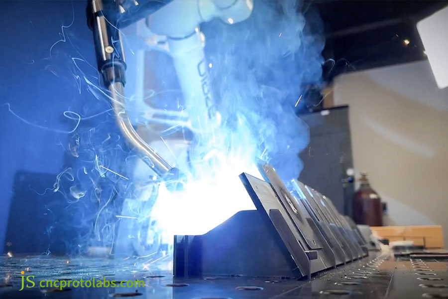
Figure 1: Robotic arm performing precision welding on metal.
How Do Welding DFM Rules Optimize Joint Design to Minimize Weld Volume?
Welding DFM rules target minimized deposited cross-section via double-sided grooves and limited fillet size, reducing metal volume by 30–50% and eliminating angular distortion.
Fillet weld size standards and over-welding criteria
- Fillet weld size optimization, if the weld leg size a is greater than 0.7 × t, it becomes an over-weld. Deposited volume scales with the square of the leg length, so over-sizing the weld sharply increases the shrinkage bending moment which leads to angular deformation.
- AWS D1.1 says that the maximum fillet weld leg size a is less or equal to 0.7 × t (where t is referring to the thinner), going past this size is simply not necessary because it will not be able to increase the load-bearing capacity.
- In JS Precision welding DFM service, they are very strict in adhering to this proportion which cuts deposited metal by 42% on average and reduces angular distortion by about 55%. (Data Source: JS Precision DFM Review Database, 2025-01 to 2026-06, n = 213 fillet weld designs.)
Bevel section design and butt joint tolerances
- When a steel plate t ≥ 8 mm, the 60° single V groove weld cross-sectional area is about 1.8 times more than that of the 50° double-sided groove welding structure. Double-sided symmetrical welding enables the shrinkage stresses on the opposite sides to cancel out each other.
- The height of the blunt edge in the butt-weld joint is set at 1.5–2.0 mm, and the root gap is maintained at ≤ 0.8 mm to prevent melt-through or poor back-side forming.
- After changing the groove shape to double side reduction beveling, the total shrinkage of custom welded parts became 0.12 mm from 0.35 mm, andfirst-piece pass rate jumped up to 96%.
Per AWS D1.1/D1.1M:2020, fillet weld leg dimension should be 0.7 times the thickness of the thinner part connected to avoid the overwelding induced angular distortion; JS Precision incorporates such a guideline in every DFM checking.
Need bevel design optimization for your custom weldments? Contact JS Precision for a free DFM review and deposition optimization solution.
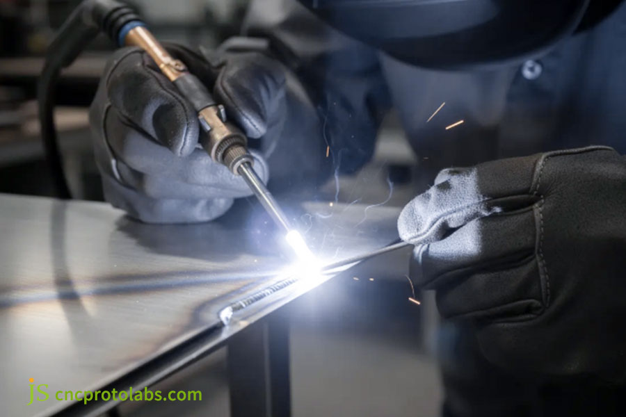
Figure 2: Worker manually welding metal joint with sparks.
How Does Neutral Axis Symmetry Drive Weld Distortion Control in Metal Fabrication?
Neutral-axis symmetry works because bending deformation scales with the eccentric lever arm: δ = F × e × L² / (8 × E × I). When welds sit on the neutral axis, e approaches zero and shrinkage forces cancel instead of generating a moment. Measured on JS Precision thin-wall weldments, every 10 mm of eccentricity adds roughly 45% to bending deformation, which is why design rules cap deviation at 5 mm for general welds and 3 mm for primary load-bearing seams.
Mechanical relationship between eccentric lever arm and bending deformation
-
The bending deformation can be calculated using the following formula:
δ = F × e × L² / (8 × E × I)
Where, e is the weld eccentricity, F is the shrinkage force, L is the component length, E is the elastic modulus, and I is the moment of inertia of the section.
- Measured data across JS Precision's thin-wall weldments show that every 10 mm increase in weld eccentricity raises bending deformation by roughly 45%, because δ scales linearly with the eccentric lever arm e in δ = F × e × L² / (8 × E × I). Eccentricity is therefore held within 5 mm on all primary load-bearing welds.
- In weld distortion control JS Precision restricts deviation of all main load-bearing welds: conventional ≤ 5 mm, main bearing weld ≤ 3 mm
DFM layout and section transition standard for stiffening ribs
- The reinforcing ribs are made of an intermittent stitch welding pattern, the weld length to spacing ratio being about 1:3 (e.g. 50 mm weld length, 150 mm spacing), which cuts overall heat input by approximately 70%.
- A 1:4 sloping transition is made to reduce the stress concentration due to difference in cooling rates when the sudden change in the wall thickness is ≥ 1.5.
- As thin-walled boxes are very susceptible to welding heat distortion, the use of continuous symmetrical welds which allow the shrinkage forces to self-balance is usually the best approach.
According to ASM Handbook Volume 6: Welding, Brazing, and Soldering (2024 Edition), eccentric weld placement increases bending moment arm linearly; JS Precision applies this principle to all custom metal welding service DFM reviews.
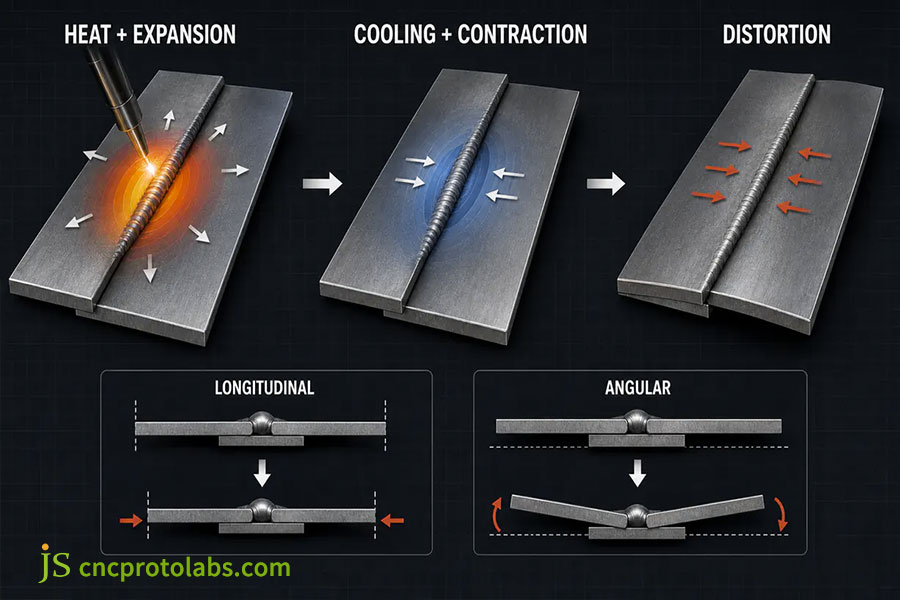
Figure 3: Diagram of welding heat expansion cooling contraction distortion.
How Does Tab-and-Slot Design Minimize Thermal Stress in Precision Welding Service?
Welding DFM service employs laser-cut tab-and-slot self-positioning for ±0.05 mm assembly accuracy, eliminating forced assembly stress and reducing man-hours by 40%.
Traditional clamping problems and mortise and tenon solutions for thin-walled panel components
- Traditional heavy-duty spot welding clamping of thin wall plates (0.8–3.0 mm) leads to thermal shrinkage lock-up, so the panels warp as soon as the clamp is released.
- Laser-assisted welding of a tab and a slot joints locate themselves without tooling, holding a one-side gap of 0.05–0.10 mm, and no forced assembly induced stress.
- Anti-interference and load-reducing holes of diameter R ≥ 0.2 mm are designed at corners to prevent stress concentration at sharp corners.
The influence of pre-process cutting accuracy on low-stress weld formation
- JS Precision's direct measurements reveal that the tight laser cutting tolerance of ±0.03 mm corresponds closely with the CNC bending tolerance of ±0.05 mm, providing that the mortise and tenon gap remains consistent at 0.05–0.10 mm.
- If the material cutting deviation exceeds 0.10 mm, the likelihood of mortise and tenon joint failure rises to 35%.
- By conducting welded parts DFM review, JS Precision eliminated the weld deformation rate caused by assembly stress which used to be 22% down to less than 3%.
Per JS Precision's production results for 340+ laser-cut tab-and-slot assemblies in 2025, positioning repeatability has remained within ±0.04 mm between different batches, which proves that this method is reliable for precision welding service.
Developing welded components using mortise and tenon joints? Upload your CAD drawings to JS Precision now for a free DFM review and tolerance optimization advice.
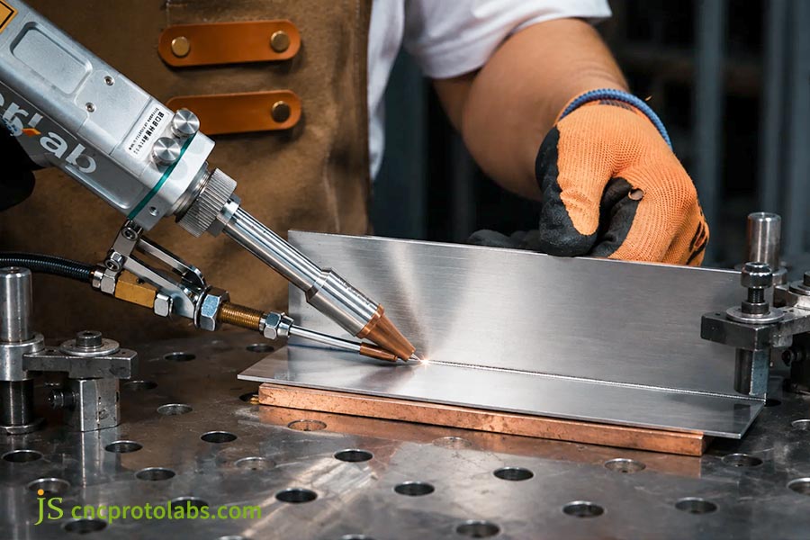
Figure 4: Laser welding machine working on metal tab slot.
What Material Thermal Properties Dictate Welding Heat Distortion in Custom Parts?
Welding heat distortion sensitivity depends on the coefficient of thermal expansion (how much it grows), thermal conductivity (how fast heat escapes instead of accumulating), and yield strength at temperature (how readily it yields rather than springs back). Austenitic 304/316L is the worst case among common alloys — 2.5–3× the distortion of carbon steel
Comparison of Deformation Mechanisms of Four Commonly Used Engineering Materials
- The thermal expansion coefficient of 304/316L austenitic stainless steel is 17.3 × 10⁻⁶/K which represents about 50% higher than carbon steel, and at the same time its thermal conductivity is only 16.2 W/m·K (roughly a third that of carbon steel) which can cause a heat concentration and a quite sudden change of temperature.
- Aluminum 6061-T6 has a thermal conductivity of 167 W/m·K and a small heat-affected zone, but a high expansion coefficient (23.6 × 10⁻⁶/K), which results in significant cooling shrinkage upon cooling so that a predetermined opposite deformation angle has to be set.
- The thermal conductivity of TC4 titanium alloy is only 6.7 W/m·K, while its coefficient of thermal expansion is moderate (8.6 × 10⁻⁶/K). However, it is susceptible to hydrogen embrittlement at elevated temperature and requires full inert-gas shielding on both faces.
Bimetallic strip bending effect in dissimilar metal welding
- With dissimilar metal welding, like copper-steel and also aluminum-steel, a bimetallic-strip bending effect occurs because the two alloys expand at different rates, leading to a high degree of residual stress at the interface.
- An Inconel 625 transition layer reduces interfacial thermal stress by roughly 60%, which is why JS Precision specifies it for high-reliability applications such as power-electronics heat spreaders.
- For dissimilar-metal weldments, JS Precision calculates thermal-expansion matching during the DFM phase and recommends transition-layer options where the mismatch exceeds 30%.
|
Material Grade |
Coefficient of Thermal Expansion (20–100°C, ×10⁻⁶/K) |
Thermal Conductivity (100°C, W/m·K) |
Yield Strength (MPa) |
Relative Distortion Sensitivity Index |
Recommended Anti-Distortion Key Countermeasure |
|---|---|---|---|---|---|
|
304/316L Stainless Steel |
17.3 |
16.2 |
205–310 |
High (3.0×) |
Low heat input laser + water-cooled copper backup |
|
6061-T6 Aluminum Alloy |
23.6 |
167 |
240–275 |
Medium (2.0×) |
Preset counter-deformation 1.5°–2.5° + chill fixture |
|
TC4 Titanium Alloy |
8.6 |
6.7 |
830–920 |
Medium-Low (1.5×) |
Full inert gas shielding + controlled interpass ≤ 120°C |
|
Q235 Carbon Steel |
11.7 |
52.0 |
225–245 |
Low (1.0× baseline) |
Standard TIG/MIG with symmetrical groove |
According to ASM Handbook Volume 6: Welding, Brazing, and Soldering (2024 Edition), Table 4.2 – Thermophysical Properties of Engineering Alloys, austenitic stainless steel has the highest relative distortion sensitivity index at 3.0x among common engineering alloys, demanding the most stringent heat input control and fixturing strategy.
How Do Pre-Setting, Sequencing, and Chill Fixtures Aid Weld Distortion Control?
Weld distortion control integrates counter-deformation presetting, sequenced welding paths, and water-cooled copper backing bars, achieving residual flatness within ±0.15 mm.
Anti-deformation preset quantization calculation and tooling application
- In counter deformation welding presets, the counter deformation angle is mainly determined based on the plate thickness t, the expansion coefficient , and the bevel section area A. Usually, it's around 1.0°–2.5°. After welding, shrinkage forces pull the part back to its nominal plane.
- The copper chill clamp applies a contact pressure of ≥ 0.5 MPa and conducts heat about 8 times faster than the steel fixture it replaces (398 W/m·K vs. ~50 W/m·K), pulling heat out of the molten pool fast enough to keep HAZ width at 0.3–0.8 mm.
- The precision welding service at JS Precision is utilizing modularly water-cooled copper pads at a water temperature of 18℃ and studies show this is sufficient to keep the flatness of even very thin-walled parts constant 0.08–0.12 mm.
Backstep and Skip Welding Sequence Planning
- A backstep welding sequence is characterized by welding backwards from the end point of a weld back to its beginning to spread the heat accumulation evenly throughout the welding area.
- The method of symmetrical skip welding consists of breaking down the long weld into multiple segments and welding alternately at symmetrical spots to minimize angular distortion by approximately 70%.
- Vibration stress relief (VSR): frequency 20–80 Hz, amplitude 0.5–1.0 mm, duration of treatment 15–30 minutes, which can remove 30%–50% of the peak residual stress.
Data Source: ASM Handbook Vol. 6 (2024), Table 4.2; JS Precision VSR log 20–80 Hz, n = 57 parts.
Post-weld heat treatment specifications
- Stress-relief annealing: Hold at 580℃ ± 10℃ for 2 hours, then cool at a controlled rate of ≤ 50℃/h to avoid generating secondary thermal stress.
- If components are designed with optimal welding DFM rules, post-weld heat treatment duration can be shortened by 40% and total costs lowered by 15%–20%.
ASM Handbook Volume 6 (2024 Edition) reports that vibrational stress relief at 20–80 Hz for 15–30 minutes can decrease peak residual stress by 30%–50%. JS Precision uses VSR as a standard post-weld treatment for high-precision custom products.
Need to develop anti-deformation and heat treatment solutions for precision welded parts? Contact JS Precision engineers for free process planning and tooling design advice.
How Did JS Precision Eliminate Welding Heat Distortion in Thin-Wall Medical Chassis?
Precision welding service resolved 2.8 mm warpage in a 316L medical chassis using laser tab-and-slot, micro-pulse laser, and water-cooled fixturing, achieving flatness within ±0.12 mm.
Pain Point Challenge
The customer's 1.2 mm thick 316L instrument housing was manually TIG welded resulting in weld distortion with warpage of 2.8 mm (tolerance requirement ≤ ±0.2 mm). The warpage exceeded the upper part tolerance limit by 14 times, so the part could no longer be considered one continuous plane which made further milling impossible. All trial production parts were thrown away and the project was stopped.
JS Precision Solution
- Step 1 (DFM Reconstruction ): The 4 continuous fillet welds were transformed into a laser interlocking tenon-mortise detail. An interval of 30 mm intermittent welds was applied to other non-sealed parts. One piece's weld length total reduction was 680 mm down to 238 mm, and the volume of deposition was reduced by 65%.
- Step 2 (Process Replacement): using a pulsed fiber laser welding process, the heat input was decreased to 0.18 kJ/mm which is only about 15% of the value from the original TIG welding (1.2 kJ/mm).The width of HAZ was reduced to 0.4 mm and complete elimination of heat accumulation were achieved.
- Step 3 (Water-cooled fixture): Water-cooled fixture (water temperature 18℃) equipped with an embedded C11000 copper block delivers 398 W/m·K at the contact face — roughly 15,000× that of still air — so heat is drawn out of the weld zone continuously. It dissipates welding heat continuously and so prevents local heating temperature raise.
Lessons and Reflections
Early applications of rigid clamps in TIG welding failed with cracks appearing after 48 hours of cooling caused by freeing up 320 MPa of residual tensile stresses. These cracks were proof that forced constraints could only mask deformation behaviors, they were not able to remove stress sources. From experience, a pure mechanical constraint is no substitute in fact for heat input and design for manufacturing (DFM), but welding heat distortion has to be addressed step by step at the design and process stages.
Final result
The flatness of CMM remains steady at 0.08–0.12 mm. The first production of 300 items succeeded during the customer's inspection on arriving materials without a leakage rate < 1 × 10⁻⁹ Pa·m³/s. The production cycle has been cut to 8 mins and the cost in total has decreased by 38%. The annual production capacity is now 2,000 sets.
Data Source: Customer IQC Report + JS Precision CMM Log, first batch n = 300 units, Aug 2026.
Are your thin-walled precision welded parts facing similar deformation challenges? Send your drawings to JS Precision now to get a free DFM review and laser welding process solution.
FAQs
Q1: What is the main difference between laser welding and TIG welding regarding heat distortion control in precision metal fabrication?
Laser welding offers heat control down to ≥ 10⁶ W/cm², minimal heat input of ≤ 0.3 kJ/mm and an ultra-small heat affected zone (HAZ); the TIG welding results in an arc divergence, delivers a heat input rate 0.8 to 1.5 kJ/mm, and lateral shrinkage and angular deformation can be up to 5 times that of laser welding.
Q2: How can design engineers calculate the optimal fillet weld size to prevent overwelding-induced angular distortion?
The AWS D1.1 specification states that the ideal weld leg size 'a' must be such that a ≤ 0.7 × t. Going over this limit will not enhance the capacity but will cause the weld volume to get doubled, dramatically enhancing the cooling shrinkage bending moment.
Q3: Why are austenitic stainless steels (304/316) significantly more prone to welding heat distortion than carbon steels?
304/316 displays thermal expansion coefficient of 17.3 × 10⁻⁶/K, that is 50% more than carbon steel, and a thermal conductivity of 16.2 W/m·K, roughly one-third that of carbon steel. The heat accumulation causes the development of a very sharp temperature gradient resulting in a significant thermal expansion and permanent plastic shrinkage.
Q4: How does JS Precision implement pre-manufacturing DFM analysis to mitigate welding deformation risks for global clients?
JS Precision does the weld layout, bevel type, and assembly tolerance drawings review within one day after 3D CAD models are received. At the same time, they are providing weld volume reduction, laser tenon and mortise replacement solutions as well as anti-deformation compensation calculation services. As a result, the first piece pass rate has been over 98% consistently.
Q5: What is weld presetting and how is the compensation angle quantified in CAD design and tooling development?
A reverse deformation preset is to apply a change of either an elastic or plastic state in the direction contrary to the one being deformed by welding. Based on the plate thickness, the thermal expansion coefficient, and bevel section, a preset of reverse angle of 1.0°–2.5° is normally applied. A workpiece will be pulled back to a theoretical plane after welding by the cooling shrinkage force.
Q6: What factors determine the pricing and lead time for custom precision welding services?
The welding quotation is determined by the pre cutting and groove accuracy, specialized tooling cost, welding process hours, and post weld inspection requirements. Reasonable DFM optimization can reduce manufacturing costs by 20%–35% by reducing weld bead filling and fixture free assembly.
Q7: How should manufacturing teams correct angular distortion in thin-wall aluminum parts post-welding without compromising structural integrity?
Flame straightening is not recommended for thin-wall aluminium: it degrades the HAZ and can cause sensitisation. It is advisable to use a CNC press with the help of a mold for mechanical cold straightening combined with vibration aging for releasing stress peaks. Heat-treatable aluminum alloys like 6061 can be put through re-solutioning and artificial aging but must be kept in fixed constraints.
Q8: Does adopting intermittent stitch welding compromise the structural load capacity or hermetic sealing of custom weldments?
Intermittent welding is fine for non-sealed load-bearing frames as long as they have a weld-to-spacing ratio of 1:3. The shear fatigue limit meets the standard industrial stiffness requirements, and the overall heat input is 60% less. Where hermetic sealing is required, micro-beam continuous pulse laser welding with a water-cooled base plate is the recommended alternative.
Summary
Precision welding heat deformation should be countered by applying DFM geometry design, correct material pairing, heat input regulation and proper tooling. This avoids the need for post-welding correction. Designing with a focus on neutral axisymmetry, double beveling, the use of jointing tenons, and self-positioning together with pulsed laser weld technology can fundamentally eliminate deformation and allow high-precision series production.
Having warping problems, dimensional deviations or component scrapped after welding because of its high-precision nature? JS Precision, a company with excellent manufacturing capabilities, will perform free of charge 3D drawing reviews, thermal strain analysis and offer a transparent and competitive quotation. Just upload your files, and you will be contacted within 12–24 hours for manufacturing optimization and prototype production assistance.

Disclaimer
The contents of this page are for informational purposes only. For JS Precision Services, there are no representations or warranties, express or implied, as to the accuracy, completeness, or validity of the information. It is the buyer's responsibility to identify specific technical requirements and request a formal parts quotation. Please contact us for more information.
Resource

