

In CNC milling services, a seemingly fundamental decision - which face milling cutter to choose, how much cutting depth to use - directly determines the accuracy, smoothness, machining efficiency, and ultimately cost of the plane.
Chatter marks, tool deflection, excessive tool wear, and even workpiece scrap can result from improper selection. The key to success is having the appropriate tooling and process strategy, whether you're looking for precision CNC milling parts with the best surface quality or need to effectively remove a lot of material from deep cavities.
In addition to demonstrating JS Precision's proficiency in this area, this guide will dissect the fundamental principles of CNC milling machining to help you steer clear of typical pitfalls and achieve the ideal balance of accuracy, efficiency, and cost, whether in prototyping or mass production.
Summary of Core Answers
| Core Challenges | Common Misconceptions | JS Precision's Professional Solutions |
| Poor Flatness and Vibration Marks | Blindly using large-diameter tools or excessive depth of cut leads to excessive cutting forces. | Based on material properties, machine tool rigidity, and target precision, scientifically calculate and recommend the optimal tool diameter-depth of cut-feed combination. |
| Low Efficiency and Precision Loss in Deep Cavity Machining | Using conventional layered milling results in excessive tool overhang, causing vibration and tool deflection. | Apply efficient strategies such as "small steps, fast runs" trochoidal milling and use extended rigid toolholders to ensure CNC milling precision. |
| High Costs for Small-Batch Prototyping | Ordering dedicated non-standard tools for prototypes or using uneconomical machining parameters. | Utilize existing standardized tool libraries and flexible processes to maximize cost savings while meeting precision CNC milling requirements. |
| Delayed Delivery for Urgent Projects | Insufficient supply chain preparation or excessively long process validation times. | Implement rapid response processes, including preparing commonly used materials, standard tools, and validated process templates, to shorten delivery cycles. |
Key Takeaways:
- Tooling is part of the system: Optimal selection depends on the combined effects of workpiece material, machine tool power/rigidity, fixture stability, and target precision.
- Depth of cut is not an isolated parameter: It needs to be optimized in conjunction with radial width and feed rate for efficient and stable cutting.
- Tailor-made strategy for deep cavities: Avoiding simple layering and employing a targeted high-performance milling (HPML) strategy is key.
- Early collaboration determines economics: Communicating manufacturability during the design phase avoids expensive tool customization and inefficient processes.
Trust JS Precision's CNC Milling Services: Overcoming The Challenges Of End Face Milling Precision
High-end manufacturing has always experienced challenges with the precision control of CNC milling. According to the ISO 8688-1 milling standard, companies often get trapped in cycles of rework, increased costs, and delays due to issues such as tool wear, thermal deformation, and chatter.
JS Precision, with over 15 years of experience in CNC milling services, has successfully solved various precision machining problems for over 500 customers worldwide, covering multiple high demand industries such as aerospace, medical equipment, and optical instruments.
Our main strength is in the implementation of the “systems thinking” approach across the entire machining process, instead of just adjusting one parameter in isolation.
For example, for one of our client’s end-face milling projects for titanium alloy components, we not only optimized the tool's material type and number of teeth but also improved machining accuracy from ±0.02 to ±0.005 mm due to our adjustment in machine tool speed, feed rate, and depth of cut. All of this resulted in a 30% improvement in tool life.
JS Precision possesses the right resources to operate a complete quality control system from the raw material warehouse to the finished product. This is made possible by the presence of high precision testing tools like laser interferometers and coordinate measuring machines.
All of our engineers have 8 or more years in dealing with Design for Manufacturing (DFM). Because of this supervising potential machining problems and offering solutions early in a project becomes possible.
So far, our machining yield rates in precision parts remain at a rate of 99.8%. This reflects highly on our reliability in the field. This, combined with our customer repurchase rate of over 75%, further strengthens our reputation in the company.
Looking to avoid precision mistakes and receive your CNC milling project in a timely manner? Reach out to the engineering team at JS Precision and let them know the part material, precision specs, and delivery time of your project, and we will give you a free process assessment and solution optimization to protect your project.
How To Select The Perfect Face Mill For Your CNC Milling Services Project?
Choosing a face mill is a balancing act of material, machine tool capabilities, and quality. This will have a direct impact on the efficiency and quality of the CNC milling services you receive.
The Mastery of Face Mill Diameter and Toothcount
Face mills have many parameters and two of those are effective diameter and tooth count. They are at the center of cutting efficiency and quality.
- Effective Diameter: Chose a diameter that is 1.2-1.5 times the workpiece width to achieve even force distribution, lower chatter, and better efficiency.
- Tooth Count Selection: Consider machine tool power and material, referring to the following table:
| Workpiece Material | Recommended Tooth Count | Key Reasons |
| Aluminum Alloy | 8-12 teeth | Low cutting resistance, improved efficiency, and smooth chip removal |
| Steel | 4-6 teeth | Large chip grooves, reducing clogging and cutting force |
| Titanium Alloy | 3-4 teeth | Good heat dissipation, prevents chip adhesion, and extends lifespan |
The Decisive Details of Insert Material and Geometry
Insert material, coating, and geometry determine cutting performance and must be matched to the machining scenario.
| Coating/Substrate | Applicable Materials | Core Advantages |
| PVD Coated Carbide | Aluminum, Stainless Steel | High hardness, low friction, anti-adhesion, suitable for high-speed cutting |
| CVD Coated Carbide | Steel, Cast Iron | Strong adhesion, wear-resistant, high-temperature resistant |
| Diamond Coated | Non-ferrous metals, Composite materials | Extremely high hardness, wear-resistant, excellent surface quality |
Influence of Insert Geometry
- Sharp Cutting Edge: Ideal for softer materials like aluminum with low cutting forces for a smooth finish.
- Reinforced Cutting Edge: Ideal for harder materials like steel and titanium alloys. Strong cutting edges that are anti-chipping.
Matching CNC milling services requirements is a must for efficiency and precision. For high precision cutting edges, choose high-precision options. For greater efficiency, choose inserts that are impact resistant.
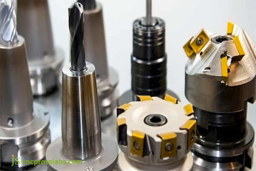
Figure 1 End face milling cutters are designed in various ways based on their geometric shapes and structures.
Critical Considerations For Deep Pocket Milling In CNC Milling Machining
Special processes are required for deep cavity milling (depth-to-width ratio exceeding 3:1). The main obstacles are insufficient tool rigidity and chip removal difficulties which require specific solutions.
Trade-Off Between Tool Rigidity and Overhang
The length-to-diameter ratio of a tool affects rigidity. If the ratio is greater than 5:1, the rigidity decreases considerably, leading to deformation, chattering, and other issues.
Solutions: Use "relay milling" where tools of different lengths are combined for machining. Also use extended rigidity toolholders that are dynamically balanced.
Strategies for Effective Chip Removal and Heat Control
Deep cavities and poor chip removal can result in secondary machining and even tool wear. Without active control, the heat build-up can result in thermal deformation.
- Chip Removal: Use helical feed, in conjunction with one or more of the following: segmented tool lifting, and optimized toolpath strategies. Pair with high pressure (10-20MPa) coolant or compressed air flushing.
- Thermal Control: Select the proper type of cutting fluid, adjust cutting parameters, and perform machining of high-precision components in a temperature controlled environment.
Do you want CNC milling machining for deep cavity components to overcome the challenges of chip removal and rigidity? Contact JS Precision, our professional team will provide customized deep cavity milling solutions based on your part aspect ratio and material characteristics, free of charge to avoid processing risks and ensure part accuracy and delivery efficiency.
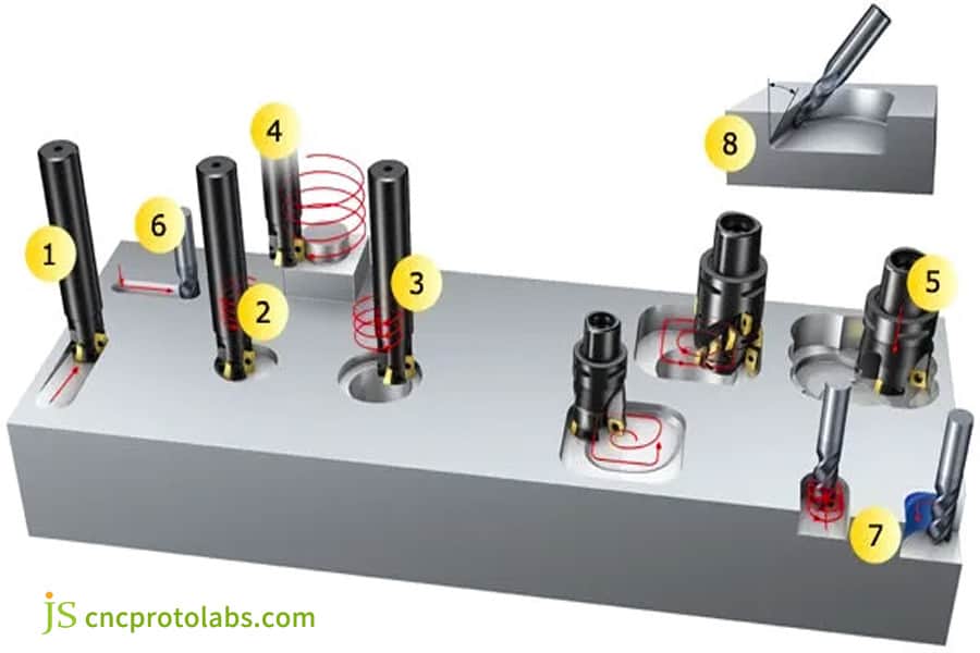
Figure 2 Milling holes and cavities,pockets
The Precision Equation: Optimizing Depth Of Cut For Unmatched CNC Milling Precision
The Depth of Cut (Ap) must adhere to the cutting parameters established within the ISO 3685 standard. This is a primary parameter for accuracy, surface finish, and efficiency and must be optimized with the particular stage of machining and the characteristics of the system.
The Depth of Cut Philosophy of Roughing and Finishing
The goals of roughing and finishing are quite distinct, and the depth of cut strategies are therefore quite different.
- Rough machining: large cutting depth (tool diameter 30% -50%), moderate cutting width, fast material removal, matching machine tool and tool bearing capacity.
- Precision machining: small cutting depth (0.1-0.3mm), high speed, high feed rate, ensuring surface quality and dimensional accuracy.
Avoiding Trembling: Searching for 'Sweet Points'
Vibration affects the CNC milling precision, and adjusting the cutting depth is the key to vibration avoidance.
- Reason for vibration: Parameters such as cutting depth and speed excite resonance in the machine tool workpiece system.
- Solution: By adjusting the cutting depth to avoid resonance frequency (i.e. the sweet spot in the "stability lobe diagram"), the processing quality and efficiency can be improved.
Want to accurately find the "sweet spot" of your parts processing and achieve ultra-high CNC milling precision? Submit your part information and machining pain points, and JS Precision will use professional software for simulation analysis to provide you with customized cutting depth optimization solutions, so that your precision machining can avoid detours.
Process Optimization Strategies For Economical CNC Milling Services
The cost savings of CNC milling services come from optimizing the entire process, rather than simply lowering unit prices, which can achieve a win-win situation of cost reduction and efficiency improvement.
Tool path optimization: reducing idle running and improving cutting efficiency
Tool path optimization is the key to cost reduction and directly affects machining time and tool life.
- High speed milling (HSM): improves cutting speed while ensuring quality, making chips easy to discharge.
- Optimize cutting in and out: spiral cutting and arc cutting to reduce blade damage.
- Dynamic milling: Constant cutting load, reducing running and improving efficiency.
Hidden cost control of materials and clamping
The utilization rate of materials and clamping time are implicit costs, which can be significantly reduced after optimization.
- Material optimization: Intelligent typesetting improves board utilization and matches standard raw material specifications.
- Clamping optimization: Using modular fixtures to reduce replacement and debugging time, suitable for small and medium-sized production.
From Prototype To Production: Balancing Cost And Accuracy For Precision CNC Milling Parts
Prototype production of precision CNC milling parts needs to balance cost and accuracy, laying the groundwork for mass production and achieving a smooth transition from prototype to mass production.
The "Good Enough" Principle in the Prototyping Phase
The core of the prototyping phase is functional verification. Extreme precision is not required, costs can be controlled through the "good enough" principle.
- Relax tolerances for non-critical dimensions to reduce machining difficulty.
- Use standard cutting tools to avoid the high cost and long lead times of custom tools.
- Use easily machinable alternative materials for functional verification.
Design Scalability Considerations
Prototype design must consider Demanufacturability (DFM) to ensure a smooth transition to precision CNC milling services mass production.
- Avoid structures requiring special cutting tools, such as extreme aspect ratios and extremely small internal corner radii.
- Standardize dimensions such as hole diameters and fillets to adapt to standard mass production cutting tools and fixtures.
Struggling with the transition from prototyping to mass production for precision CNC milling parts? Upload your prototype design drawings, and JS Precision's DFM engineers will provide you with a free manufacturability analysis to help you optimize your design, balance prototyping costs and mass production feasibility, and minimize project delays.
How Expert Precision CNC Milling Services Ensure Rapid Turnaround?
Urgent projects put pressure on the supplier's planned response. Professional precision CNC milling services providers have the capability to deliver high-quality products and services very quickly because of their use of standard processes and technologies.
Fast Track process and reserved resources
JS Precision introduces the Quick-Turn Protocol to make sure that urgent projects continue to move forward.
- Priority Scheduling: Opens up a fast track that guarantees the availability of resources.
- Dedicated Communication: A project manager is available around the clock to provide updates on the progress of the project.
- Reserved Resources: Keeps stocks of frequently used materials and standard tools, therefore avoiding delays in procurement.
Digital Simulation and First-Piece Success
Digital simulation is a technical promise for the timely delivery of urgent projects and a way of circumventing on-site debugging delays.
- Collision Simulation: Lets one foresee collision risks and, thus, guarantees machining safety.
- Time Estimation: Plans production with great accuracy to prevent delivery delays.
- First-Piece Success: Lessens debugging and, thereby, saves time.
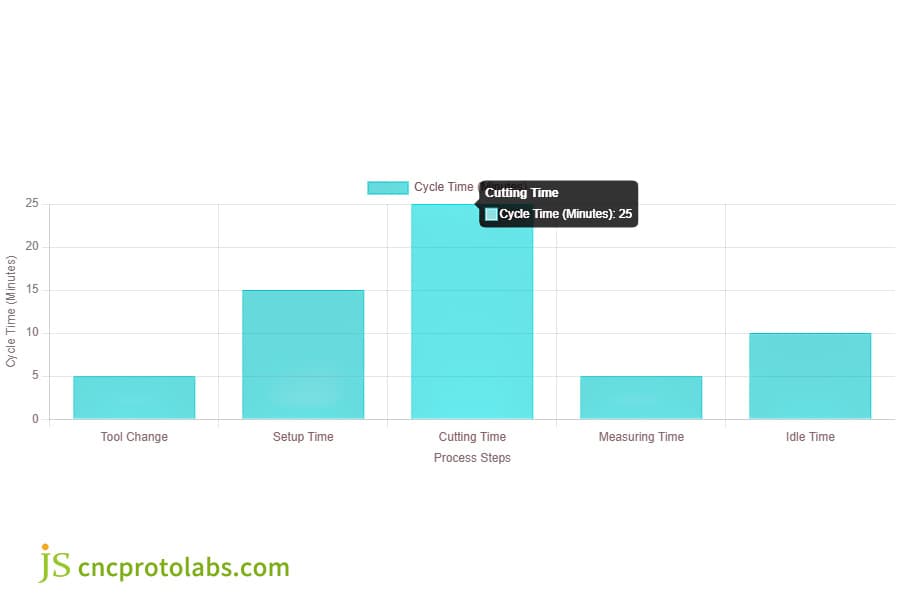
Figure 3 This bar chart shows the various components of cycle time in the CNC milling process. By analyzing and optimizing these processes, operators can significantly improve overall efficiency.
Case Study: From Chatter To Mirror Finish: Achieving Ra<0.4μm On a Large Aluminum Plate
Client and challenge:
An optical equipment manufacturer needs to process a 600mm x 400mm aluminum alloy reference platform, requiring flatness < 0.05mm and Ra < 0.4μm.
The previous supplier's process issues resulted in vibration marks and non-compliance with flatness standards, putting the project on the verge of cancellation. They urgently need a reliable precision CNC milling services provider.
JS Precision's solution:
After taking over the project, JS Precision immediately organized an engineering team to conduct a system diagnostic, ultimately identifying the root cause of the problem and developing a targeted solution.
System Diagnosis:
Through analysis, the JS Precision team determined that the previous supplier's problems mainly stemmed from two aspects.
- First, the rigidity of the tool-spindle-workpiece system was insufficient.The large-diameter, low-tooth tool used resulted in uneven force distribution during cutting, triggering resonance.
- Second, the mismatch between depth of cut, spindle speed, and feed rate further exacerbated the chatter.
Precise Measures:
- First, a smaller diameter (φ50mm) precision face cutter with more teeth (10 teeth) was used to reduce the cutting force per tooth and lower system vibration.
- Second, a stability lobe diagram was generated using specialized software, and the optimized depth of cut (0.2mm) and spindle speed (8000rpm) were recalculated and applied.
- Finally, a "climbing milling" method was used in conjunction with an ultra-high precision spindle for final finish milling, further improving surface finish.
Environmental Control:
Given that the machining of aluminum alloys can very easily be affected by temperature changes, a controlled environment (with a temperature range of ±1°C) was applied during machining operations and the MQL method was used.
This practice not only dramatically reduced the amount of cutting fluid that contaminated the surface but also managed the cutting temperature quite well, thus stopping any thermal deformation from occurring.
Results:
The very first batch of workpieces was successfully produced in one go, obtaining a flatness of 0.03mm and achieving a surface roughness of Ra 0.35μm, which resulted in a magnificent mirror finish.
The customer not only managed to save the project but also entered into a long-term partnership with JS Precision, and all the subsequent orders of high-precision platforms will be processed by us.
So far, the machining yield for this part series has stayed at an impressive 100% and the delivery cycle has been cut by 15% in comparison to the client’s original expectations.
Are you also facing the same difficulty in achieving the required accuracy for precision milling? If so, take a look at more success stories from JS Precision and find out how we deal with machining difficulties for clients across various industries. If you have particular part machining requirements, just upload your drawings with the note "precision optimization," and we shall get back to you with a free feasibility study and an exact quote.
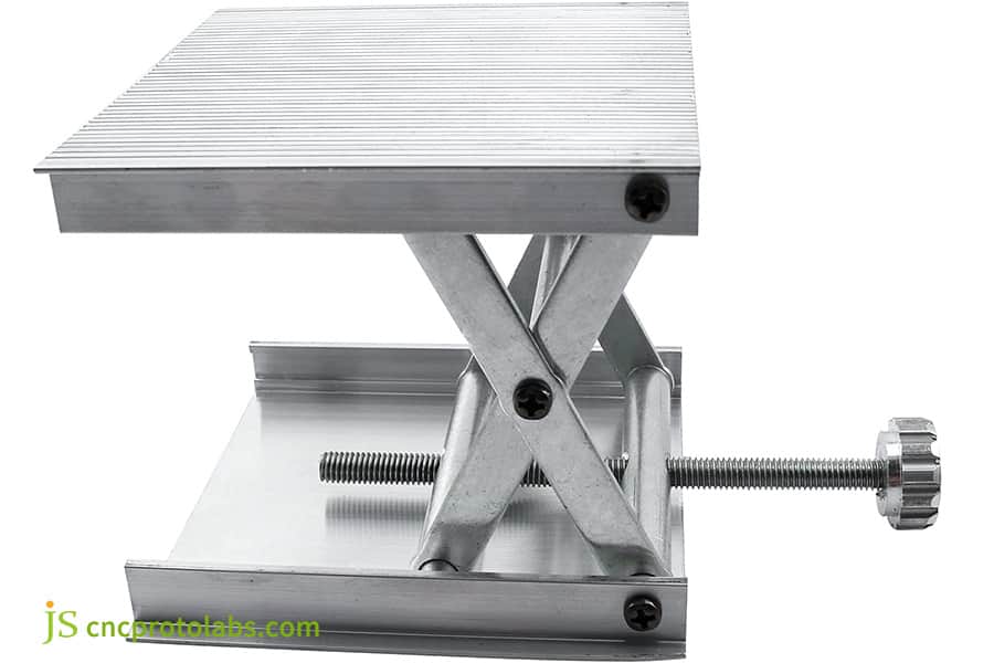
Figure 4 Aluminum alloy reference platform for optical equipment
How To Vet a Supplier For Reliable Precision CNC Milling Services
A trustworthy vendor for precision CNC milling services will eliminate the risks related to quality, cost, and delivery. However, this process requires a thorough evaluation of various aspects like technical skills, and collaboration effectiveness rather than just considering the price and machinery.
Technical Capability Assessment: Beyond the Equipment List
Evaluating technical capabilities is much more than just getting an equipment inventory: analyze the completeness of the process database, tool management system, full-process quality inspection and SPC application, and the engineering team's DFM experience. The best suppliers can compensate for processing risks beforehand.
Collaboration Transparency and Communication Efficiency
Effective collaboration is essential for the success of a project: evaluate the digital collaboration capabilities of the supplier (customer portal, progress tracking, etc.) and their communication. Put at the top of your list those partners who can be involved intimately in planning and who can timely identify and resolve issues.
FAQs
Q1: What is the biggest difference between choosing face milling cutters for machining aluminum alloys and steel?
For machining aluminum alloys, choose high-speed, multi-tooth, sharp-face milling cutters to ensure smooth chip removal and prevent chip adhesion. For machining steel, choose tough, coated, low-tooth, high-capacity chip fluting cutters to improve wear resistance and chip breaking ability to withstand high cutting forces.
Q2: When deep cavity milling, is it better to use small depth of cut multi-layer milling or large depth of cut few layers milling?
Small depth of cut multi-layer milling is recommended. It reduces cutting forces, tool deformation and chatter, facilitates chip removal, and prevents secondary cutting. Large depth of cut few layers can easily increase tool load, increase chip removal difficulty, and affect accuracy and tool life.
Q3: To achieve better surface finish, should the spindle speed be increased or the feed rate decreased?
Spindle speed and feed rate need to be optimized in tandem. First, ensure a reasonable feed per tooth, then increase the spindle speed to refine the surface texture. Simply decreasing the feed rate can easily lead to excessive friction between the tool and the workpiece, which can worsen the surface quality.
Q4: How do you handle the thermal deformation problem during machining, especially on precision parts?
Thermal deformation during precision parts machining is effectively controlled through four methods: multi-stage stress relief, matching appropriate cooling methods, rationally arranging the process sequence, and precision machining in a constant-temperature workshop.
Q5: How to prevent deformation during planar milling of thin-walled parts?
The core is to reduce cutting forces and evenly distribute clamping forces. Symmetrical machining, small depth of cut, and light cutting, combined with tooling such as vacuum chucks or elastic clamps, can effectively prevent deformation during planar milling of thin-walled parts.
Q6: What is the typical process and time from inquiry to receiving the first batch of parts?
The typical process consists of four steps: 1-2 working days for quotation confirmation, 1-3 working days for process programming, 5-10 days for prototype machining/10-25 days for mass production machining, and 1-5 days for logistics, proceeding in an orderly manner according to demand.
Q7: If I am overseas, how can I effectively communicate design details and track production progress?
Overseas clients can collaborate through a 24/7 online client portal, with a dedicated bilingual project manager, using email, video conferencing, and other methods to ensure seamless design communication and production progress tracking.
Q8: What is the most unique advantage of choosing JS Precision compared to other local or Asian suppliers?
The core advantage is the fusion of European-level technical capabilities and Asian cost advantages. This allows us to solve complex precision machining challenges, achieve low-cost and fast delivery through an efficient supply chain, and provide a seamless experience from prototype to mass production.
Summary
The selection and depth control of face milling cutters is a field where science and experience are perfectly combined in CNC milling services. It requires a deep understanding of physical principles, precise control of equipment performance, and a continuous pursuit of cost efficiency.
JS Precision, with its systems thinking at its core, uses professional technology and rich experience to safeguard your CNC milling projects.
Take your precision face machining needs to the next level now!
Visit the JS Precision website, upload your part drawings, or contact our engineering team directly. You will receive a professional CNC milling services solution including detailed process analysis and tool recommendations, and experience firsthand how we transform complex precision milling into predictable, high-quality success in your projects.

Disclaimer
The contents of this page are for informational purposes only.JS Precision Services,there are no representations or warranties, express or implied, as to the accuracy, completeness or validity of the information. It should not be inferred that a third-party supplier or manufacturer will provide performance parameters, geometric tolerances, specific design characteristics, material quality and type or workmanship through the JS Precision Network. It's the buyer's responsibility Require parts quotation Identify specific requirements for these sections.Please contact us for more information.
JS Precision Team
JS Precision is an industry-leading company, focus on custom manufacturing solutions. We have over 20 years of experience with over 5,000 customers, and we focus on high precisionCNC machining,Sheet metal manufacturing,3D printing,Injection molding,Metal stamping,and other one-stop manufacturing services.
Our factory is equipped with over 100 state-of-the-art 5-axis machining centers, ISO 9001:2015 certified. We provide fast, efficient and high-quality manufacturing solutions to customers in more than 150 countries around the world. Whether it is small volume production or large-scale customization, we can meet your needs with the fastest delivery within 24 hours. Choose JS Precision this means selection efficiency, quality and professionalism.
To learn more, visit our website:www.cncprotolabs.com
Resource